


IM-P157-38
CMGT Issue 4
20
Steam/Water Mixing Stations (MkII valves - 2002 onwards) Safety and Operation
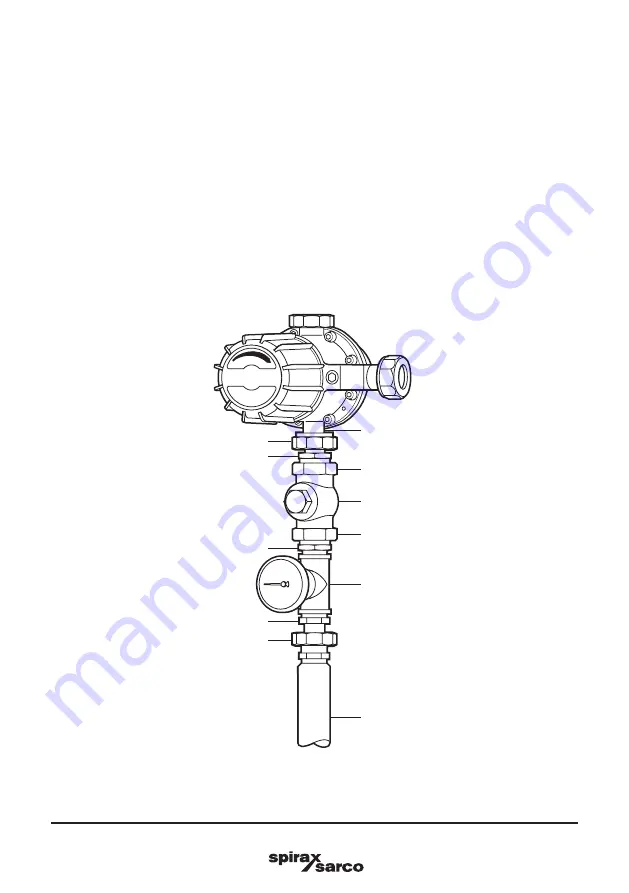
Fig. 6
INLET
OUTLET
'T' piece
Steam/water mixing valve
Reducing nipple
1" x
¾
" reducing nipple
Equal nipple
Union
TCO1
Hose (with protective sleeve)
Union
Hot water outlet
½
" and
¾
" station only
NOTE: For satisfactory hosedown purposes steam and water supplies should have a minimum
pressure of 3 bar g (43.5 psi g) and a maximum pressure of 10 bar g (145 psi g) and are required
to be nominally equal. (Please see Section 7 , 'Fault finding', for details). The minimum pressure
provides a reasonable spray velocity and flowrate at the gun (see Figure 7).
When replacing a steam/water mixing valve in a mixing valve station the spool pieces supplied must be
installed between the pressure gauge 'T' piece and the mixing valve union in the steam and cold water supply
lines. This will take account of the smaller overall dimension of the replacement valve.
Connect the pipework fittings according to Figure 4 using a suitable thread sealing medium. The TCO1 is
installed between the hot water outlet of the mixing valve and the equal 'T' that houses the thermometer. The
TCO1 is connected to the equal 'T' using a 1" x
¾
" reducing nipple. The other end is connected to the valve via
a reducing nipple and the male/female union joint on the mixing valve. Care should be taken to ensure that the
hexagon cap is in line with the dial face of the thermometer when the arrangement is tightened into the valve.
To attach the hose to the thermometer 'T' piece first screw the male/male equal nipple into the 'T' piece.
The hose is then connected to the male/male equal nipple via the female union on the hose (see Figure 6).


