background image

Instruction manual for Water-cooled Air Compressor  HV2/210                                 - 14 -

Part Qty. Description
No.

4189 34

Stud - crank case covers

4192 16

Stud - inspection hole

4193

4

Stud - bursting disk

4197

6

Stud - main bearing housing

4198

1

Stud - LP separator

4202 10

Stud - cooler cover

4204

2

Stud - cooler cover

4208 16

Stud - valve cover

4209 12

Stud - cooler cover

4215

8

Stud - cylinder block / crank case

4219

6

Stud - cylinder top

4236

4

Nut - drain plate

4237 34

Nut - crank case cover

4238 32

Nut - inspection hatch, cooler cover

4240 44

Nut - cooler cover, valve cover

4242

6

Nut - cylinder top

4253

6

Locknut - main bearings

4257

8

Locknut - cylinder block / crank case

4268

1

Set screw - counter weight

4269

1

Nipple

4271

4

Nipple

4273

2

Nipple

4275

1

Nipple - c.w. inlet

4276

1

Nipple - c.w. outlet

4280

2

Nipple

4294

3

Plug

4296

7

Plug

4297

1

Plug

4298

1

Plug

4361

1

Pressure gauge tube

4364

2

Pressure gauge tube

4367

1

Pressure gauge tube

4372

3

Nipple

4374

1

Reduction nipple

4388

1

Lub. oil tube

4391

1

Lub. oil tube

4407

2

Screw - counterweight

4414

2

Washer - pressure gauge panel

4416

8

Washer - cooler cover

4420

1

Safety valve, HP

4421

1

Safety valve, LP

4433

4

Screw - non return valve cover

4441

1

Lub. oil pump

4446

1

Set screw

4447

1

Set screw

4449

2

Screw

4451

2

Connecting nipple

4471

2

T-joint

4487

6

Coupling bolt

4523

1

Coupling disk

4624

4

Screw - non return valve flange

4673

2

Screw - gudgeon pin bearing

7591

1

Cooler cover - Pos. 2

7593

1

Cooler cover - Pos. 4

7595

1

Separator

7609

1

Cyclone pipe

7620

6

Stud - cooler cover Pos. 2

7645

1

Drain plate

Part Qty. Description
No.

7648

1

Gasket - drain plate

7651

1

Drain trap

7654

1

Drain nipple

7655

1

Guide pin

7657

1

Plug

7659

1

Cap nut

7660

1

Gasket

7664

4

Stud - drain plate

7665

2

Swivel nipple

7747

6

Stud - cooler cover Pos. 4

7750

2

Plug

7754

1

Nipple

Valve parts:

3012

1

Delivery valve, HP complete

3020

1

Suction valve, LP complete

3021

1

Delivery valve, LP complete

3043

1

Valve gripper, LP complete

3049

1

Suction valve, HP complete

3061

1

Valve seat, HP suction

3062

1

Valve seat, HP delivery

3069

1

Valve seat, LP suction

3070

1

Valve seat, LP delivery

3087

2

Damping plate, LP

3092

3

Valve spring, HP suction

3106

2

Valve plate, HP valve

3109

2

Valve plate, LP valve

3133

2

Valve washer

3135

1

Valve washer

3141

1

Fixing pin

3142

1

Fixing pin

3145

2

Fixing pin

3146

2

Fixing pin

3161

1

Valve catcher, HP suction

3162

1

Valve catcher, HP delivery

3167

1

Valve catcher, LP suction

3168

1

Valve catcher, LP delivery

3181

1

Valve spacer ring

3182

1

Valve spacer ring

3186

3

Valve spacer ring

3187

1

Valve spacer ring

3206

1

Valve bolt, HP suction

3207

1

Valve bolt, HP delivery

3214

1

Valve bolt, LP delivery

3218

1

Valve bolt, LP suction

3237

2

Valve nut

3238

2

Valve nut

3260

6

Valve spring, HP delivery

3265

6

Valve spring, LP suction/delivery

Summary of Contents for HV2/210

Page 1: ...dustri sperre com Sperre Rotterdam BV Tel 31 180 463 299 Fax 31 180 463 264 E mail rotterdam sperre com Sperre Asia PTE LTD Tel 65 763 63 00 Fax 65 763 18 11 E mail asia sperre com Sole suppliers of g...

Page 2: ...ce of the equipment Keep the compressor in good mechanical order and remember that proper preventive maintenance of the equipment will reduce the risk of damage and unnecessary shutdowns The manufactu...

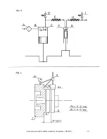
Page 3: ...he low pressure stage LP and the second is the high pressure stage HP Air circulation through the compressor is shown in Fig 3 The letters indicate A Suction filter B LP suction valve C LP delivery va...

Page 4: ...n in Fig 4 Use vernier callipers or inside micrometer callipers to check the distance W Fig 4 This should be the same around the whole circumference of the coupling Using a micrometer A check the radi...

Page 5: ...f cooling water temperature However additional regular checking of operation and automatic functions is recommended Some water form the compressed air will always condence in the system The compressor...

Page 6: ...es require maintenance too frequently Possible cause Remedy Overheating Check cooling water circulation and temp Inspect coolers and clean if necessary Dirty intake air Check suction filter Inferior l...

Page 7: ...important to adapt the maintenance schedule to the experience of the individual operator Maintenance Maintenance intervals routine Daily A Every 500 hours B Every 1000 hours C Every 3000 hours D Ever...

Page 8: ...eck them carefully IMPORTANT Never use sharp implements on sealing surfaces and plate parts C Replace all parts that are worn or even slightly scored Check that all guide pins are in order Maximum wea...

Page 9: ...il BP ENERGOL RC 68 BP ENERSYN RX 100 CASTROL AIRCOL PD 100 CASTROL AIRCOL SN 100 CALTEX RPM COMPR OIL 68 CHEVRON HD COMPR OIL 100 ESSO EXXON EXXCOLUB 77 DAPHNE MARINE COMPRESSOR 100 FINA EOLAN AC ELF...

Page 10: ...one coupling half Dismantle the coupling A Loosen the nuts on each coupling half and give each one a sharp tap with a hammer before removing them completely This will cause the bolts to loosen from th...

Page 11: ...O rings type OF special quality Use only manufacturer s spares To remove the tube bundle first loosen the cooler covers at both ends The whole bundle can then be withdrawn by means of two guide rods...

Page 12: ...ended limit switch setting for lube oil pressure safety stop 0 8 bars Normal working pressure one stage 0 10 bars 1 5 3 5 bars Normal working pressure one stage 10 35 bars 4 0 6 0 bars Maximum working...

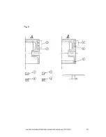
Page 13: ...bearing shaft clearance mm 0 08 0 12 Crankshaft bearing play mm 0 08 0 11 Gudgeon pin bearing play mm 0 03 0 04 T 5 Piston rings Pressure stage LP HP Piston illustration F 5 B A Number of compressor r...

Page 14: ...oil pump 3583 1 Valve spring lub oil pump 3606 1 Adjusting screw lub oil pump 3634 1 Oil level gauge glas 3643 1 Pressure gauge board 3654 2 Cooler unit 3677 1 Key Part Qty Description No 3696 3 Cap...

Page 15: ...bolt 4523 1 Coupling disk 4624 4 Screw non return valve flange 4673 2 Screw gudgeon pin bearing 7591 1 Cooler cover Pos 2 7593 1 Cooler cover Pos 4 7595 1 Separator 7609 1 Cyclone pipe 7620 6 Stud co...

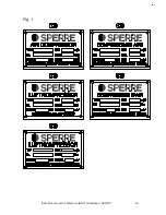
Page 16: ...Fig 1 Instruction manual for Water cooled Air Compressor HV2 210 15...

Page 17: ...Instruction manual for Water cooled Air Compressor HV2 210 16...

Page 18: ...Instruction manual for Water cooled Air Compressor HV2 210 17...

Page 19: ...Instruction manual for Water cooled Air Compressor HV2 210 18...

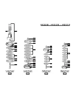
Page 20: ...HV2 200 HV2 210 HV2 219 NOV 2001 Low pressure suction valve Low pressure delivery valve High pressure suction valve High pressure delivery valve...

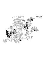
Page 21: ...73 7651 7591 4271 3927 4416 7655 7595 4202 4238 4240 4198 7620 3932 7657 7660 7659 7665 4296 3519 3505 3533 3398 3468 3486 4204 4238 4624 3716 4053 4433 1366 3906 2998 7609 3906 4240 7747 7593 3932 76...

Reviews: