SURVIVAIR Opti-Fit
™
Convertible Facepiece
25
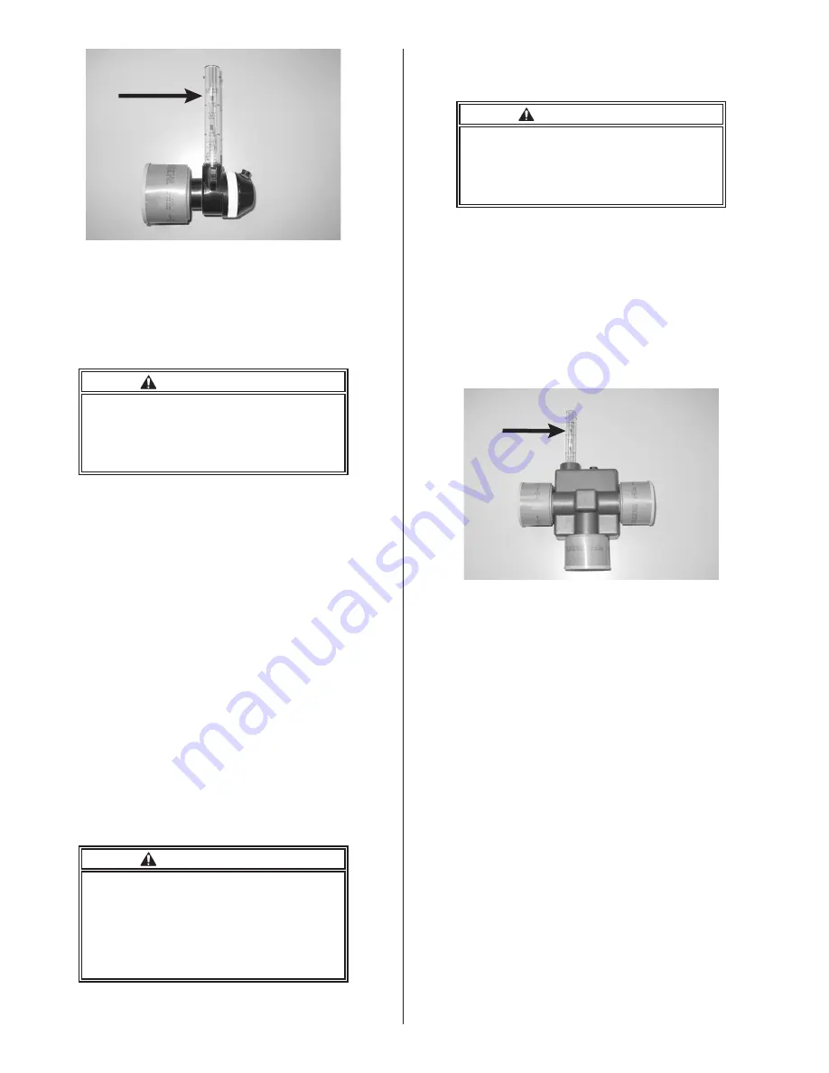
Figure 21. Flow Meter Attached
to Mask-mounted Blower
4. If the ball rises above the line on the flow me
-
ter indicating that the flow exceeds 4 cubic
feet per minute, proceed to the step 6.
WARNING
If the flow meter ball does not rise above
the line, DO NOT USE the PAPR until the
cause can be determined and corrected.
Use of a PAPR with a low flow may re
-
sult in illness or death.
5. If the ball is below the line indicating low
flow, the most probable causes are:
a. The filter is blocked by dust or water.
Replace with a new SPERIAN HE filter,
P/N 108000.
b. Low battery voltage. Recharge the bat-
tery for 14 to 16 hours.
Identify and correct any low flow problems
before proceeding to step 6.
6. Remove the flow meter and detach the
power cord from the battery pack. Reat-
tach the blower to the facepiece, ensuring
that the catch snaps into the slot on the
facepiece nozzle.
7. Slip the belt through the loops on the bat-
tery pack and adjust the battery pack so
that the belt rides comfortably on the hips.
Tighten the belt.
8. Attach the power cord to the battery pack.
WARNING
If changing the filter and/or recharging
the battery pack does not restore normal
airflow, DO NOT USE the PAPR. Have the
PAPR repaired by the SPERIAN factory
repair center.
Using a PAPR that is operating improp-
erly may result in illness or death.
b. Belt-mounted PAPR Configuration–Pre-opera
-
tional Flow Check
WARNING
Flow check, facepiece fit check, don
-
ning, and doffing must be done in a safe,
uncontaminated area. Failure to comply
with this warning may lead to personal
injury, illness, or death.
The airflow must be verified before each use.
Use the following procedure to verify that the
blower is supplying adequate airflow.
1. Verify the tightness of all three (3) cartridges
or filters.
2. Insert the Flow Meter, P/N 580009, into
the blower outlet with the arrow pointing
upward as shown in Figure 22.
Figure 22. Flow Meter Attached
to Belt-Mounted Blower
3. Connect the power cord to the battery pack
and blower assembly, and start the blower
by pressing the battery ON/OFF switch.
NOTE
Do not cover the inlet area of any cartridges,
filters, or slots in the side of the flow meter
tube when performing the airflow check.
4. Verify the airflow is greater than 170 liters
per minute (6 cfm) at the blower outlet
as shown in Figure 22. The flow meter is
designed so that a reading of 170 lpm or
greater at the blower outlet will ensure the
airflow is greater than 115 lpm at the full
facepiece. If the ball rises above the line
on the flow meter indicating that the flow
exceeds 170 lpm, proceed to step 6.


