SLS SERIES MANUAL
III
118132-001 RevA
LIST OF FIGURES
Figure 2.1
SLS Series Dimensions ...............................................................................6
Figure 3.1
SLS Series Typical Operating Set Up .........................................................10
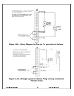
Figure 3.2A
Wiring Diagram for Remote Programming via Voltage Source ................12
Figure 3.2B
Wiring Diagram for Remote Programming via External Resistance ..........12
Figure 3.3
Remote Monitor Test Points .......................................................................13
Figure 3.4
Remote Control of High Voltage On and Off ............................................13
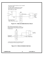
Figure 3.5
External Inhibit Interface Circuit ................................................................14
Figure 3.6
External Interlock Interface Circuit ............................................................14
Figure 3.7
Remote High Voltage On and Off Indicator Circuit ....................................... 15
Figure 3.8
Remote Indicators Interface ............................................................................ 16
Figure 5.7
Instant On Option ............................................................................................ 21
LIST OF TABLES
Table 1.1
SLS Options ................................................................................................3
Table 3.1
System Cables .............................................................................................11
Table 3.2
Rear Panel Interface 25 pin Mini D Connecter Pin Out .............................12
APPENDIX
A.
Specification Controls (Custom Models Only)


