background image

8

SPEKTRUM DX5C • TRANSMITTER INSTRUCTION MANUAL

EN

TRAVEL

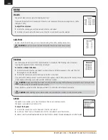
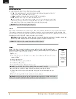
The Servo Setup menu contains the following functions:

Travel sets the overall travel or endpoints of the servo arm movement. Travel values range from 0–150% 
(Default is 100%).

To adjust Travel values:

1. 

Scroll to the channel you wish to adjust and click the scroll wheel. 

2. 

Scroll Up or Down to adjust the travel value. Click the scroll wheel to save the selection.

SUB-TRIM

Subtrim offsets the entire range of servo travel including the center and endpoint positions.

CAUTION

 Use only small sub-trim values may affect travel if full servo travel is used.

REVERSE

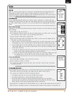
Use the Reverse menu to reverse the channel direction. For example, if the Steering servo moves Left, 
reversing the channel will move the Steering servo Right.

To reverse a channel direction:

1. 

Scroll to Travel and click the scroll wheel. Scroll up or down until Reverse appears, then click the scroll 
wheel again to save the selection.

2. 

Scroll to the channel you wish to reverse and click the scroll wheel.

If you reverse the Throttle channel, a confi rmation screen appears. Select YES to reverse the channel. A second 
screen appears, reminding you to bind your transmitter and receiver. 

CAUTION: 

Always rebind the transmitter and receiver after reversing the Throttle channel. Failure to do so will result in the 

throttle moving to full throttle if failsafe activates.

Always perform a control test after making adjustments to confi rm the vehicle responds properly.

CAUTION: 

After adjusting servos, always rebind the transmitter and receiver to set the failsafe position.

SPEED

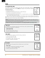
The Speed menu enables you to slow the response time on any individual channel.

The Speed is adjustable from 100% to 1%.

To adjust the Speed:

1. 

Scroll to the channel you wish to adjust and click the scroll wheel.

2. 

Scroll Up or Down to adjust the speed and click the scroll wheel to save the selection.

3. 

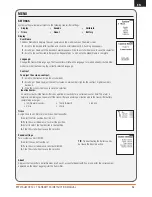
Select a switch to activate/deactivate the function. If Switch ON is selected, the value will always be on for that function.

MENU

Summary of Contents for DX5C

Page 1: ...Instruction Manual Bedienungsanleitung Manuel d utilisation Manuale di istruzioni DX5C 5 Channel 2 4GHz DSMR Radio System ...

Page 2: ...arged prior to using the model Always check all servos and their connections prior to each run Never operate your model near spectators parking areas or any other area that could result in injury to people or damage of property Never operate your model during adverse weather conditions Poor visibility can cause disorientation and loss of control of your model Never point the transmitter antenna di...

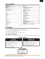
Page 3: ...ter first 2 Turn on vehicle 3 Turn off vehicle first 4 Turn off transmitter For AVC equipped vehicles let the vehicle remain still until the radio is connected Receiver installation 4 Identifying Controls and Switches 5 Installing Batteries 5 Main Screen 5 Navigation 6 Using the Scroll wheel Selector 6 Individual Direction Adjustments 6 Auto Switch Select 6 Switch Selection tip 6 Click 6 Scroll 6 Ho...

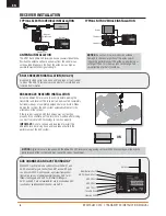
Page 4: ...ntenna tube Make sure the tip of the antenna is as high as posible to maximize the signal strength SR415 RECEVIER INSTALLATION NO AVC Use double sided servo tape hook and loop tape or foam rubber to mount the SR415 reciever securely where it is protected and isolated from vibration TYPICAL ELECTRIC VEHICLE INSTALLATION TYPICAL NITRO VEHICLE INSTALLATION Receiver Motor Electronic Speed Control Stee...

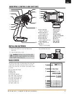
Page 5: ...n E Default Steering Rate Up F Trimmer Button F Default Brake Rate Up G Button G Default Timer Start Stop H Power Button I Roller Wheel J Antenna K Steering Wheel L Trigger throttle brake M Battery Door N Data Port O LCD Screen P Back Button Q Clear Button The Main Screen displays information about the active model including the Timer when activated To return to the Main Screen at any time press a...

Page 6: ...ove the control in that direction 4 Click the scroll wheel to save the selection To Enter Select or Exit a selection To move between options or change values in an option Hold for 6 seconds and release to return to the Main screen SCROLL HOLD CLICK NAVIGATION Tip The tick mark below shows the current switch position Rolling and clicking the scroll wheel turns the selected box black indicating that...

Page 7: ...ay cause loss of vehicle control damage or personal injury MENU Click the scroll wheel from the main screen to access the FUNCTION LIST The FUNCTION LIST contains all the available menus on the DX5R The functions include Model Select Model Name Travel Sub Trim Reverse Speed Rates Exponential Timer Bind Frame Rate Mixing AVC Trim Setup Aux Assign Settings Utilities MODEL NAME Model Name enables you...

Page 8: ...e scroll wheel again to save the selection 2 Scroll to the channel you wish to reverse and click the scroll wheel If you reverse the Throttle channel a confirmation screen appears Select YES to reverse the channel A second screen appears reminding you to bind your transmitter and receiver CAUTION Always rebind the transmitter and receiver after reversing the Throttle channel Failure to do so will r...

Page 9: ...e default position for this function is inhibited The Exponential Expo function affects the response rate of the steering throttle and or brake A positive Steering Expo value for example decreases steering sensitivity around neutral to make it easier to drive at high speeds in a straight line while still allowing for maximum turning radius While sensitivity with positive Expo is decreased around n...

Page 10: ...the receiver will drive the throttle servo to its pre programmed failsafe posi tion normally full brakes and all other channels will have no servo output The throttle failsafe position is set during binding If the receiver is turned on prior to turning on the transmitter the receiver will enter the failsafe mode driving the throttle servo to its preset failsafe position When the transmitter is tur...

Page 11: ...on for the second servo appear when the switch position setting Pos is assigned to a switch position Front only and Rear only steering options do not have rate or trim options 1 Use the scroll wheel to select the travel settings turn the wheel to adjust travel for each side individually Setting this value positive or negative determines the second servo direction 2 Use the scroll wheel to select t...

Page 12: ...ly OTF feature for each AVC value Click on the arrow to the right of the switch selection to set the trimmer to increase or decrease the gain from the set value Tip Trimmers can only be assigned to one OTF function Steering and throttle gain values cannot be adjusted from one trimmer button TIP For receivers withoutAVC leave theAVC menu in the DX5C inhibited INH TRIM SETUP Trim Setup affects the a...

Page 13: ...er numbers darken it 3 Click the scroll wheel once to save the selection Display Trims Sounds About Calibrate Battery Inactive Alarm An alarm activates if the transmitter sees a period of inactivity for a certain amount of time The alarm is helpful in reminding you to power off the transmitter and avoiding a situation where the transmitter battery completely discharges Inh No alarm sounds 5 min 10...

Page 14: ...smitter returns to the Main Screen 3 Add a new model by rolling to the bottom of the list You will then be prompted with the Create New Model screen CAUTION NEVER change the model in Model Select while operating a model Changing the model memory interrupts the transmitter signal to the receiver and may cause loss of vehicle control damage or personal injury In the Model Utilities function you can ...

Page 15: ...tion This is helpful to group similar models together to make them easy to find To move a model highlight the model that you wish to move with the scroll wheel then click the scroll wheel to select it Scroll the scroll wheel to move the selected model to the position desired Click the scroll wheel when you have the model in the position desired The Model Copy menu enables you to duplicate model pro...

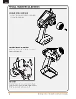
Page 16: ...teering wheel STANDARD WHEEL CONVERSION STEERING TENSION ADJUSTMENT Turn the screw clockwise with a small Phillips screw driver to increase the steering tension DATA PORT The data port gives drivers access to future updates Register ing the transmitter is neccesart for updates Updates require the SPMA3065 updater cable not included and a PC DATA PORT ...

Page 17: ...mechanical brake very little servo travel is used to apply braking force In this case it is common to reduce throttle travel for braking well below 80 To calibrate a vehicle with a mechanical brake increase the brake travel above 80 whenever the vehicle is calibrated bound then change the braking travel back to the travel setting for your brakes NOTICE The following sequence of steps must be follo...

Page 18: ...eer in an effort to get back to the original heading When driving heading hold only works when the steering wheel is left straight The moment you begin to turn the wheel heading hold turns off When the wheel is re centered heading hold is turned back on AVC TUNING PROCEDURE 1 With the transmitter and receiver already bound and properly calibrated turn on the transmitter and vehicle 2 Apply throttl...

Page 19: ...er to receiver Can t assign functions to the desired switches or buttons Buttons and or switches are already assigned to another function Re assign functions to other buttons or switches to free up the switch so it can be assigned to your designated function Function requires a switch or trimmer but tons have limited functionality Select a switch or trimmer if your designated function will not wor...

Page 20: ...on to better answer your questions and service you in the event that you may need any assistance For questions or assistance please visit our website at www horizonhobby com submit a Product Support Inquiry or call the toll free telephone number referenced in the Warranty and Service Contact Information section to speak with a Product Support representative Inspection or Services If this Product n...

Page 21: ...ers hands wrists ankles and feet and the antenna to meet RF exposure safety requirements as determined by FCC regulations The illustrations show the approximate 5 cm RF exposure area and typical hand placement when operating your Spektrum transmitter This device complies with Industry Canada license exempt RSS standard s Operation is subject to the following two conditions 1 this device may not ca...

Page 22: ...ve Vehicle Control are trademarks or registered trademarks of Horizon Hobby LLC The Spektrum trademark is used with permission of Bachmann Industries Inc All other trademarks service marks and logos are property of their respective owners US 9 320 977 10 17 ...

Reviews: