SpectraPure
SpectraPure®Inc.
480.894.5437 Call us toll-free 1.800.685.2783
2167 East Fifth St, Tempe, Arizona 85281
®
8
STEP 6: At this stage, the system will start producing water out of the 1/4” blue and 3/8” yellow lines. Discard that water
for approx. 15-20 min.
(The recirc pump produces a loud noise due to the pump size and flow rate for
membrane. This is normal.)
STEP 7:
PRESSURE ADJUSTMENT USING THE PRESSURE REGULATOR:
(show in picture)
A. The Pressure Regulator, when pushed down, is in the lock position. Pull out on it to release lock.
B. While the system is producing water, turn the Pressure Regulator clockwise to increase pressure or
counter clockwise to decrease pressure. Set the pressure to 100 PSI. Then, re-lock the pressure knob.
STEP 8:
ADJUSTING THE CONCENTRATE TO PURIFIED WATER RATIO:
If not enough concentrate is allowed to leave the system during operation, impurities will
precipitate out on the membrane surface, clogging the RO Membrane. To keep this from happening, the
Concentrate to Purified Water Ratio must be checked and adjusted in order to compensate for pressure and
temperature variations that exist in all water supplies.
The flow rate of the concentrate should be equal
to the product flow rate (1:1). NOTE: If your tap water TDS reading is below 500 PPM, you can adjust
the waste: product ratio to 1:2.
a. Hold both 1/4” blue and 3/8” yellow lines side-by-side and observe the flow rates.
b. Slowly adjust the waste flow adjustment valve (W.F. Adj, shown on page 6) until the flows appear to be
equal. NOTE:
The waste flow can be slightly less than the product.
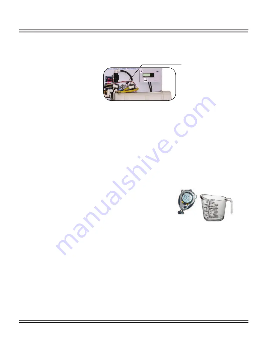
c. Get two measuring cups and a stop watch to measure the waste and product water. Make sure you have
equal measurements and adjust accordingly.
Note: NEVER close the W.F. Adj valve, completely blocking
any waste flow. This will damage the membrane and
void any warranty.
This procedure will assure you of maximum life and reliability of your SpectraPure System. Failure to perform this
procedure can permanently damage the membrane and will void the pro-rated Membrane Warranty.
STEP 9: After you adjust the flow rate, follow STEP 7 again, if needed, to assure that the system is operating with 100 PSI.
STEP 10: RE-INSTALLING AND FLUSHING DI CARTRIDGES:
A. Disconnect power to the system and shut down the water supply line.
B. Unscrew the third clear housing and install the MaxCap Cartridge.
NOTE: at this time leave the fourth clear housing empty.
C. Turn on supply line and plug power back to system. Allow water to run through the MaxCap Cartridge,
and down the drain, until the second meter (POSITIONED “IN”) reads “0”.
D. Then, follow step A and place the Silica-Buster in the fourth clear housing.
E. Finally,
turn the supply line back on, plug the power back in and allow the water to run through the
Silica-Buster Cartridge, and down the drain, until the second meter (POSITIONED “OUT”) reads “0”.
PRESSURE
REGULATOR


