background image

SpectraPure

®

SpectraPure

®

Inc.


480.894.5437   Call us toll-free  1.800.685.2783    

2167 East Fifth St,    Tempe, Arizona   85281

21

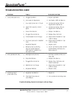
TROUBLESHOOTING GUIDE

Problem

Cause

Corrective Action

1. Low production rate.

a. Plugged prefilters.

i. Replace prefilters.

b. Low water temperature.

ii. Use higher GPD membrane.

c. Low water pressure (< 40 psi).

iii. Use booster pump OR use 

higher GPD membrane.

d. High TDS content (< 1000 

ppm).

iv. Use booster pump OR use 

higher GPD membrane.

e. Fouled membrane.

v. Replace membrane.

f.  Plugged flow restrictor.

vi. Replace flow restrictor

g. Tank bladder lost air charge.

vii. Repressurize bladder to 7 psi 

(when empty).

h. Too much pressure in bladder 

tank.

viii. Repressurize bladder to 7 psi  

(when empty).

i.

Ruptured bladder.

ix. Replace tank.

j.

Backpressure exerted by 
the pressurized bladder 
tank causes a reduction in 
production rate.

x. Use of  permeate pump retrofit 

kit (PPRFK-DI) eliminates the 
back pressure.

2.  Zero production rate.

a. Missing flow restrictor.

i. Put flow restrictor in the red 

brine line.

b. Dried membrane.

ii. Replace membrane.

c. Plugged flow restrictor.

iii. Replace flow restrictor and 

check membrane.

d. Bladder lost air charge.

iv. Repressurize bladder to 7 psi 

(when empty).

e. Ruptured bladder.

v. Replace tank.

3. Extremely high 

production rate.

a. Ruptured membrane.

i. Replace it.

b. Very high line pressure  

(over 80 psi).

ii. Use a pressure reducing valve.

Troubleshooting Guide Continued on Next Page.

Summary of Contents for DWS Series

Page 1: ...allation Failure to follow any attached instructions or operating parameters may lead to the product s failure and possible damage to property SpectraPure Inc assumes no responsibility for water damage due to leaks It is the user s responsibility to determine that the system is leak free 06 24 2020 MPDW 90 DWS 90 DWS PP 90 ...

Page 2: ...umbing Schematic 10 DWS 90 Plumbing Schematic 10 DWS PP 90 Plumbing Schematic 11 System Installation Working With Push Fittings 11 Preparation 12 Drill Hole for Faucet in a Porcelain Sink 12 Punch Hole for Faucet in Stainless Steel Sink 12 Feed Supply Valve Installation 13 Air Gap Faucet Installation DWS 90 and DWS PP 90 14 Non Air Gap Faucet Installation MPDW 90 15 Drain Saddle Installation 16 Wa...

Page 3: ...Maximum Iron 0 1 ppm Maximum Manganese 0 1 ppm Maximum Hydrogen Sulfide 0 ppm Langelier Saturation Index LSI must be negative SAFETY PRECAUTIONS Failure to follow the listed precautions may result in bodily injury equipment damage and or loss of warranty coverage WARNING Do not mount your water purification system above an electrical outlet Leakage may cause the outlet to short circuit and could p...

Page 4: ...so reduce the amount of particulates microscopic cysts lead volatile organic compounds VOCs and other contaminants 3rd Stage RO Membrane After passing through the two prefilters the water then passes through the Reverse Osmosis RO membrane With a pore size of 0 0001 microns 0 00000004 inches the RO membrane is capable of removing over 99 of TDS Total Dissolved Solids in the water After passing thr...

Page 5: ...nstallation instructions AIR GAP FAUCET DWS 90 and DWS PP 90 See page 14 for installation instructions NON AIR GAP FAUCET MPDW See page 15 for installation instructions INCLUDED COMPONENTS continued RIGHT ANGLE PUSH FITTING ADAPTER For installation on Feed Water Inlet of Sediment Filter housing See Common Connections on page 7 STEM ADAPTER MPDW ONLY Adapts Faucet Tubing Adapter for 1 4 tubing See ...

Page 6: ... 10 INLINE POST CARBON FILTER CF IN 10 4JG PRESSURE GAUGE 18 H x 14 W x 6 5 D DWS 90 RO MEMBRANE INSIDE HOUSING MEM 0090 SEDIMENT FILTER SF MT 0 5 10 CARBON FILTER CF 0 5 10 POST CARBON FILTER CF OCB 10 PRESSURE GAUGE 15 5 H x 14 W x 8 D DWS PP 90 DWS PP 90 RO MEMBRANE INSIDE HOUSING MEM 0090 SEDIMENT FILTER SF MT 0 5 10 CARBON FILTER CF 0 5 10 POST CARBON FILTER CF OCB 10 PERMEATE PUMP PRESSURE G...

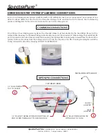
Page 7: ...ust be attached to the Feed Water IN port of the sediment filter housing The threaded fitting is attached to one end of the included 1 4 Black tubing The Feed Water IN port is located on the side of the sediment filter housing the leftmost filter housing when viewed from the front of the system Remove the elbow from the tubing and screw it into the IN port on the filter housing Hand tighten until ...

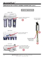
Page 8: ...NECTIONS cont 3 8 BLUE TUBING FROM TEE FITTING OUT TO TANK 3 8 BLUE TUBING FROM ELBOW FITTING OUT TO FAUCET 1 4 YELLOW TUBING FROM UNION FITTING AT END OF RED TUBING OUT TO SHORT BARB FITTING ON AIR GAP FAUCET REAR VIEW TOP VIEW FRONT VIEW DWS 90 CONNECTIONS 2 1 2 1 3 8 BLACK TUBING CONNECTS FROM LONGER BARB TO DRAIN SADDLE AIR GAP FAUCET CONNECTIONS ...

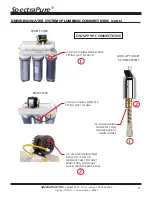
Page 9: ...YSTEMS PLUMBING CONNECTIONS cont DWS PP 90 CONNECTIONS 1 3 8 BLUE TUBING FROM ELBOW FITTING OUT TO FAUCET 3 8 BLUE TUBING FROM TEE FITTING OUT TO TANK 1 4 YELLOW TUBING FROM BRINE OUT PORT ON PERMEATE PUMP TO SHORT BARB FITTING ON AIR GAP FAUCET REMOVE BLUE PLUG 2 1 3 8 BLACK TUBING CONNECTS FROM LONGER BARB TO DRAIN SADDLE AIR GAP FAUCET CONNECTIONS 2 ...

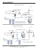
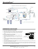
Page 10: ...UCING TEE DRINKING WATER SYSTEM DWS 90 1 LB CHECK VALVE NOTE ARROW ON CHECK VALVE MUST POINT IN SAME DIRECTION AS THE FLOW OF WATER TOWARD THE ASO VALVE CARBON FILTER SEDIMENT FILTER 2 0 4 6 8 10 11 B A R psi 100 x kPa 80 100 120 140 160 60 40 20 0 RO MEMBRANE FLOW ASO VALVE TAP WATER IN FEED WATER ADAPTER BLADDER TANK BALL VALVE DRAIN SADDLE IN PORT OUT PORT STEM REDUCER STEM REDUCER FAUCET ADAPT...

Page 11: ...le the push fitting collar is depressed pull the tubing straight out of the push fitting Once the tubing is removed release the collar To reinsert the tubing into its push fitting 1 Moisten the O ring seal inside the push fitting by dripping a few drops of clean water into the fitting 2 Grasp the tubing near the end and insert the tubing into the push fitting 3 Push the tubing into the fitting unt...

Page 12: ...ng from the installation of the faucet When drilling allow cool down time for drill bit so that it does not overheat and crack porcelain A gurgling sound may be heard coming from the Air Gap Faucet when the system is running This is normal and is in compliance with UPC Codes STEP 1 Determine a desired location for the faucet on your sink and place a piece of masking tape on the location where the ...

Page 13: ...leeve b Insert the 1 4 Black Tubing into the Compression Nut with the threads towards the end of the tube c Slip the Conical Compression Sleeve onto the Black Tube with the long slope pointing toward the end of the tube d Place the Insert into the end of the Black Tubing Make sure you push the insert in all the way e Tighten Compression Nut back on the Valve body STEP 5 When installation of the va...

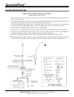
Page 14: ...uence over the threaded shaft and temporarily hand tighten then screw the push fitting onto the end of the threaded shaft D Insert the Blue 3 8 tubing into the Quick Connect Tubing Adapter E Connect the 1 4 yellow tubing to the smaller barb and connect the 3 8 Black tubing to the larger barb F Drop the entire assembly into the hole resting on the chrome counter plate Loosen the nut and position th...

Page 15: ...d tighten C Insert the Blue Tube into the Compression Nut with the threads towards the end of the tube Then add the Compression Sleeve D Place the Insert into the end of the Blue Tubing Make sure you push the insert in all the way Screw the Compression Nut onto the threaded shaft E Securely tighten both hex nut and Compression Nut F DO NOT CUT EXCESS TUBING AT THIS POINT YOU WILL NEED THE TUBING T...

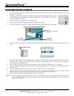
Page 16: ...tic nipple and the newly drilled hole in the drain pipe 7 Install the back half of the drain saddle and clamp assembly to drain pipe by screwing in the mounting bolts until snug WASTE WATER LINE INSTALLATION See Drinking Water Systems Plumbing Connections on Pages 6 8 NOTE The tubing must be as SHORT and STRAIGHT as possible to allow for proper drainage and reduce the noise of the Air Gap faucet 1...

Page 17: ...o the Drain Saddle ICE MAKER HOOKUP OPTIONAL Part No IMK UNIV 1 Turn off feed supply valve and the ball valve on tank Open the faucet to relieve pressure 2 Locate the Blue tube that leads to the faucet 3 Cut the tube and reconnect the cut ends with a Tee 4 Connect 1 4 Tubing to the third leg of the tee and route to refrigerator 5 Close the faucet turn on feed supply valve and open the ball valve o...

Page 18: ...When the membrane is aligned with the hole firmly push the membrane into the hole until it bottoms out 8 Place the black housing O ring on the housing rim and carefully screw the lid back on to the base 9 Reconnect the black tubing to the membrane feed push fitting and insert the membrane housing back into the retention clips 10 Close the faucet open the ball valve on the tank and turn the water s...

Page 19: ... tighten housing 5 Install carbon block prefilter in appropriate housing making sure O ring and black gaskets are in place Hand tighten housing 6 DWS 90 DWS PP 90 Install GAC carbon post filter in rightmost housing making sure O ring and black gaskets are in place Hand tighten housing 7 MPDW 90 Disconnect blue lines from inline carbon filter See page 5 for location remove the filter from the clips...

Page 20: ...on the bracket keeping the one with the bleach on the left side 8 Close the dispenser faucet put lever in DOWN position 9 Open feed supply valve 1 4 turn from closed position 10 Allow 15 minutes for the bleach solution to flow through the system Open the dispenser faucet and keep the lever in the UP position until some bleach solution is dispensed through the faucet IMMEDIATELY close the faucet as...

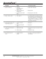
Page 21: ... psi when empty h Too much pressure in bladder tank viii Repressurize bladder to 7 psi when empty i Ruptured bladder ix Replace tank j Backpressure exerted by the pressurized bladder tank causes a reduction in production rate x Use of permeate pump retrofit kit PPRFK DI eliminates the back pressure 2 Zero production rate a Missing flow restrictor i Put flow restrictor in the red brine line b Dried...

Page 22: ...n the system is a normal occurrence with initial start up of the RO DI system This milky appearance will disappear during normal use within 1 2 weeks If condition reoccurs after filter changes drain tank 1 to 2 times 6 Reject yellow line never stops flowing water a Faulty 1 lb check valve i Replace it b Faulty auto shut off valve ii Replace it 7 Leak around the base of the spout a Displaced O ring...

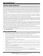
Page 23: ...uous or repeated seepage or leakage of water or the presence or condensation of humidity moisture or vapor that occurs over a period of 14 days or more Fungus and fungi mean any type or form of fungus or Mycota or any byproduct or type of infestation produced by such fungus or Mycota including but not limited to mold mildew mycotoxins spores scents or any biogenic aerosols SpectraPure will not be ...

Page 24: ...ratio recommended for water 180 ppm REPLACEMENT PARTS FOR DWS DWS PP Part Number Part Description SF MT 0 5 10 Sediment Filter 0 5 micron Sediment Filter 1st Stage CF 0 5 10 Carbon Filter 0 5 micron Carbon Block Prefilter 2nd Stage MEM 0090 90 GPD RO Membrane 90 gpd 340 lpd TFC Membrane 3rd Stage CF OCB 10 10 GAC Post Filter Polishes water and removes taste 4th Stage FR 90 RED GRN Flow Restrictor ...

Reviews: