background image

29


SHURFLO PUMP WON

T RUN


If the pump has power to it (the fan runs), but the pump won

t run, first check the pressure 

switch.


 The pressure switch (EL

-

FP

-

PS) is located on the wet end of the pump and has two red 

wires plugged into it. Jump the two red wires together and see if the pump runs. You can safe-
ly run the system with the pressure switch jumped, just keep an eye on the pressure gauge 
and don

t let system pressure exceed 110 PSI. Replace the switch when a spare is available. 

The pressure switch should never open unless there is a problem with the system or it is incor-
rectly adjusted. Check the accumulator pressure, the operating feed pressure, and the switch 
cut

-

out setting 

-

 bulletins: Misc

-

3, Misc

-

4, and SF

-

2.


If the pump will not run with the pressure switch jumped then it is most likely a problem with 
the brushes or overheat protection switch inside the motor. The motor will come completely 
apart by removing the two screws on the end of the motor. Remove the rear cover and paper 
insulator. Pull out the plastic brush holder. The thermal switch is located on one of the brush 
leads. With an ohmmeter, check for continuity through the switch. If it is open, you can make 
temporary repairs by wiring around it, being careful that your new wiring doesn

t chafe on the 

moving parts, nor resist the springs that push the brushes on to the commutator. The overheat 
switch is unlikely to fail unless the motor has overheated and shut down. Consider relocating 
the pump or improving ventilation if the overheat protection has failed.


If any corrosion is apparent the brushes may be sticking. Once apart clean all the carbon dust 
from all the parts. Clean the commutator with light sandpaper. Make sure to clean the small 
grooves on the commutator with a small sharp tool to remove the carbon in between the seg-
ments. Adjust the springs on the brush holders so the brushes slide smoothly in and out. If the 
bearings are rough and binding, remove the rubber dust cover and clean the best you can, 
grease them, and work them free by hand. Don't service the bearing unless absolutely neces-
sary. Reassemble in reverse order. You can hold the carbon brushes back with papers clips in-
serted through the slots in the brush holder so they don't hang up on the bearing during as-
sembly. Make sure the corrugated bearing shim doesn't push out, if it does, push it back into 
place.


This may keep you going until the motor can be replaced. 


5/23/14


Summary of Contents for Aquifer AF-200-DC

Page 1: ...1 Katadyn Desalination LLC Spectra Watermakers PH 415 526 2780 FX 415 526 2787 www spectrawatermakers com Revised March 2020 Aquifer Series Manual For model numbers AF 200 DC AF 360 DC AF 200 PPS...

Page 2: ...2...

Page 3: ...1 Normal Operation 12 Maintenance 18 Service Maintenance Short Term Storage Procedures 15 Introduction to Spectra Chemicals 16 Long Term Storage 17 Winterizing 18 Maintenance 19 Membrane Cleaning 20 S...

Page 4: ...list Study the system layout diagram component photos and descriptions before beginning your installation This will assist you in understanding the function of each component Getting Started Aquifer...

Page 5: ...ed brine The brine contains whatever was separated from the product water by the membrane and nothing is retained inside the machine Feed water is filtered using a three stage process A strainer first...

Page 6: ...termaker can be operated directly from the battery for two or more hours without an external power source In order to prevent damage to the watermaker the feed water should never contain chlorine blea...

Page 7: ...7 Feed Water Strainer 5 micron filter Spectra Clark Pump and Membrane assembly Pressure Relief Valve Brine Outlet Aquifer Feed Plumbing Schematic Quick Disconnect Gauge panel Accumulator Feed Pump...

Page 8: ...essure on it DO NOT feed the product into a manifold or the bottom of a tank Make sure that there is no possible restriction in this piping Note The product flow meter displays the flow per hour In no...

Page 9: ...ug in the sand which will fill with clean water The water flowing into the pit can be used as feed water and the water will be quite clean after the system has been running for a short time SETTING UP...

Page 10: ...C Power cord for the battery charger is supplied with a US style plug though it will accept any input voltage from 100 260 Volts AC 50 60Hz Aquifer Power Pack models are shipped with the battery disco...

Page 11: ...the pressure relief valve is open 1 2 turn Connect to a DC power source the solar panel or plug into AC source or depending on which unit you have 2 Turn on the feed water pump Check that it is primed...

Page 12: ...ush the salt water out of the watermaker Use only water directly from the watermaker or unchlorinated water for flushing 2 Install the intake service hose and place it in the bucket Start the feed pum...

Page 13: ...e used to flush the salt water out of the watermaker Use only unchlorinated water for flushing 2 Install the intake service hose and place it in the bucket Start the feed pump 3 Flush until container...

Page 14: ...ed water for flushing 2 Install the intake service hose and place it in the bucket Start the feed pump 3 Flush until container is empty note the pressure will drop on the gauge indicating that the mem...

Page 15: ...pt ready for immediate use indefinitely After five days if the watermaker has not been used repeat the flush process using unchlorin ated water A charcoal carbon filter can be used to remove chlorine...

Page 16: ...sed to winterize RV s boats and cabins Propylene glycol also works very well for preventing biological growth in warm climates and is good for one year See Win terizing with Antifreeze OP 1 document o...

Page 17: ...water and put it in a bucket 2 Place the end of the feed hose in the bucket and the brine hose to drain 3 Start and run the feed pump until you have one gallon 4 ltrs of fresh water left in the bucke...

Page 18: ...nd circulate the remaining antifreeze for a few minutes until well mixed 7 Stop the feed pump and discard any antifreeze remaining in the bucket 8 Blow out or drain the product tubing as it will not c...

Page 19: ...ty Occasionally lightly lube the filter housing O ring with silicone grease General Periodically inspect the entire system for leakage and chafe on the tubing and hoses Repair any leaks you find as so...

Page 20: ...C 2 Alkaline Cleaning Compound If known bio fouling is present the SC 2 may be used first Using hot water if possible up to 100 38C is recommended as it greatly enhances the ability of the cleaners to...

Page 21: ...chlorine free fresh water 2 Flush the system as shown in the Normal Operation Section Leave one Gallon of water in the bucket 3 Place the inlet service hose brine discharge service hose and product ho...

Page 22: ...s tools and membrane cleaning chemicals Spectra Watermakers parts list Part Number SC 1 STORAGE COMPOUND KIT CHEM SC1 SC 2 ALKALINE CLEANING COMPOUND KIT CHEM SC2 SC 3 SCID CLEANING COMPOUND KIT CHEM...

Page 23: ...ainer or prefilter clogged Service prefilter and strainer Low water production Low pressure Pressure relief valve partially open Worn pump head Close valve Check flow should be 1 4 GPM Replace pump he...

Page 24: ...t in flush water They must be of proper specifica tion to be suitable There is no test for chlorine damage except the process of elimina tion of other causes DIRTY OR SCALED membranes A dirty foreign...

Page 25: ...ure cutout switch PL PMP SFPH is set to 125 PSI 8 6 bar With the pump running close the brine service valve The feed pressure should rise to 125 PSI 8 6 bar then the pump should shut off If the pump s...

Page 26: ...roduct flow to the total feed flow Product flow should be 9 5 of total flow for an Aquifer 200 or 360 If product percentage is low you may have an internal leak in the Clark Pump For every 1 10 th of...

Page 27: ...all and give it a few coats of wax If the o rings are damaged or the unit has been leaking install new o rings using a little silicone grease to ease assembly These are standard o rings and should be...

Page 28: ...y will drop and the system pressure will change dramatically If the pressure gauge was installed before the prefilters as pictured in this manual the pressure will increase If the pressure gauge was i...

Page 29: ...eck for continuity through the switch If it is open you can make temporary repairs by wiring around it being careful that your new wiring doesn t chafe on the moving parts nor resist the springs that...

Page 30: ...om cutting out each time the Clark pump shifts For all systems except the Gulfstream the feed pump pressure switches should be set as fol lows On the very center of the switch is a small 5 64 Allen sc...

Page 31: ...31...

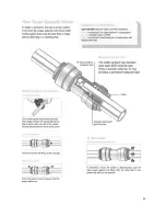
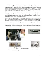
Page 32: ...gs on the 90 degree fittings on the back of the Clark Pump have captive nuts and washers which compress the O rings without turning the entire fitting If a tube fitting leaks it can sometimes be resea...

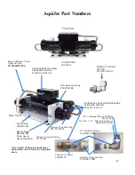
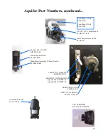
Page 33: ...o Pressure Vessel Upper SS Tube PL TB HPTPVUS Aquifer Part Numbers Stainless Fitting Hex Nut PL HWR 1 2HN 1 2 Stainless Ferrule PL HWR 1 2FR Connector O RING SO HPP CT 3 4 16 Straight Thread O RING SO...

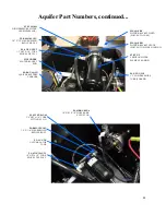
Page 34: ...EL BAT AQCG AQUIFER BATTERY CHARGER FT PV ER MEMBRANE END RING PL MTS 3 8X1 2B 3 8 NPT X 1 2 TUBE FITTING ST PL HP 1 8 1 8 HEX PLUG NYLON FT PV 20 20 HIGH PRESSURE VESSEL FM PVB PBE PLATE BRACKET END...

Page 35: ...G AQUIFER BATTERY CHARGER PL NLT 1 2LP 1 2 LOW PRESSURE TUBE PARKER PL HBE 1 8X1 4 1 8 NPT X 1 4 HOSE BARB ELL NYLON PL ACC TK ACCUMULATOR TANK PL BSH 1 2X1 4N 1 2 X 1 4 HEX BUSHING REDUCER NYL FM AQ...

Page 36: ...BE EL PL FTE 1 4X1 4P ACCUMULATOR PL ACC TK Feed Pump 12Volt EL FP 12V Feed Pump 24Volt EL FP 24V 3 8 NPT X 5 8 Hose Barb El PL HBE 3 8X5 8 Feed Pump Pressure Switch EL FP PS SEA STRAINER KIT AQ STNAS...

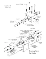
Page 37: ...37 HP TB VEB B HP TB VB HP TB VEB A HP TB BV HP CB CB10 HP CYL SST HP CYL R HP CYL EC HP CYL CCA Not used...

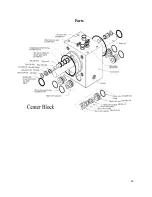
Page 38: ...38 HD CPS 5 16X3 KIT HP 10VSA HP TB ARP SO HPP AR1 SO HPP RV HP TB BV HD CPS 5 162 75 SO HPP SP HP TB VSP HP TB SR SO HPP VB SO HPP PLP SO HPP VP...

Page 39: ...39 Parts 1...

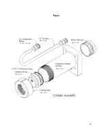
Page 40: ...40 PL MTS 3 8X1 2B HP CYL SST HP CYL CCA SO HPP ECCB HP CYL EC HP CYL R HP CYL PT Parts...

Reviews: