background image

P

OINT

CTRL

V

IRTUAL

R

EALITY

C

ONTROL

D

EVICE

S

PEC

T

ECH

D

ESIGN

M

ANUFACTURING

A

ND

T

RAINING

FCU 

O

PERATION

- LED T

IME OUT

E

NTER

S

ET

-U

P

M

ODE

C

OUNT

F

LASHES

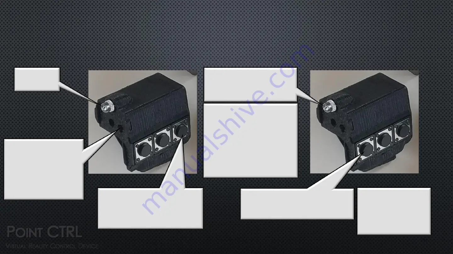
IR LED

Step (2)

Press and Hold for        

1 Second

IRLED will rapidly flash 

for 1 second 

confirming you are in 

LED Timeout mode

Step (3)

IR LED Flashes 

Once per second

Step (4)

As soon as the desired time out is 

reached press FCU BTN 3 to save

Step(1) 

Press and Hold FCU BTN 1 

before and while turning on 

FCU

Each Flash represents 10 

seconds of LED Timeout

Example

4 flashes = 40 

seconds of inactivity 

before the LED turns off.

The LED is turned on by 

pressing any of the three 

buttons

LED will flash rapidly 

and then turn off 

confirming LED Time 

Out is set. Press any 

BTN to turn on LED

11

Summary of Contents for PointCTRL

Page 1: ...Spec Tech Design Manufacturing and Training FIRMWARE VERSION 071619 SET UP AND OPERATION 1...

Page 2: ...ing FCU s FCU LED Time Out FCU Brightness Mouse Wheel Emulation Mounting HMS IR Room Survey Calibration Overview V R View User Menu Initial Calibration Edge Calibration FCU Zoom DCU Button Mapping Cal...

Page 3: ...ry reset is now for Rift S DCS centered windowed view FCU Proximity Zoom OFF Left Mouse Button FCU Button 1 Forward Most Button Improved FCU button zoom FCU buttons 1 and 2 must be pressed simultaneou...

Page 4: ...sensor is mounted to the Virtual Reality headset and tracks the position of each IR LED mounted to the FCU s The location of the on screen cursor in the virtual reality environment corresponds to whe...

Page 5: ...mel MCU 2 4GHZ transceiver 850nm LED three tactile pushbuttons and an 150mah onboard rechargeable lithium polymer battery HMS or the Head Mounted Sensor consist of a PixArt proprietary optical trackin...

Page 6: ...RTUAL REALITY CONTROL DEVICE SPEC TECH DESIGN MANUFACTURING AND TRAINING COMPONETS HMS Head Mounted Sensor FCU Finger Control Unit 3Meter Micro USB Cable Lipo Battery Charger Lipo Safe Bag Attachment...

Page 7: ...black buttons on the HMS while pressing and releasing the white reset button After successful reset the cursor will move from the left edge of the field of view to the right edge as confirmation Fact...

Page 8: ...NTROL DEVICE SPEC TECH DESIGN MANUFACTURING AND TRAINING FCU FINGER CONTROL UNIT IR LED Charging Jack ON OFF Strap Adjustment Slots Elastic Strap FCU Button 3 Mouse Wheel FCU Button 2 Right Mouse BTN...

Page 9: ...ION POWER ON OFF TURN ON TURN OFF IR LED Press and Hold for 1Second Until IRLED Lights IR LED Press and Hold for 3 Seconds Until IRLED Turns Off Must wait 4 seconds after turning FCU OFF before turnin...

Page 10: ...ing Indicator Red Light On Battery Fully Charged or No Battery Connected Light Off Battery is Charging LiPo Safe Charging Bag 10 LiPo Battery Safety Care must be taken when using Lithium polymer batte...

Page 11: ...mode Step 3 IR LED Flashes Once per second Step 4 As soon as the desired time out is reached press FCU BTN 3 to save Step 1 Press and Hold FCU BTN 1 before and while turning on FCU Each Flash represen...

Page 12: ...will Slowly din and then get bright again confirming you are in LED Brightness Adjustment Mode Step 3 IR LED will display currently set brightness Step 3A Press to Brighten LED Step 1 Press and Hold F...

Page 13: ...Functionality Emulation Direction The Mouse Wheel Button 3 will Emulate the Mouse Movement Direction of the Last Pressed BTN 1 or 2 Press to Set mouse Wheel Direction Mode to Backward BTN 1 BTN 2 Emu...

Page 14: ...llel to your line of sight before making contact with tape Cut and Fit DS Tape Cut and fit double sided tape to HMS Mount Sensor Firmly Attach Sensor and secure micro USB cable with zip ties 14 Test F...

Page 15: ...ving FCU to Confirm Limits HMS On indicator Red Glow ON Survey Room Rotate Sensor While Seated in Flying Position to Check for Stray IR Light Occlude Any Detected IR Sources IR and USB indicator Green...

Page 16: ...movement to the DCS window Your HMD screens limits must be defined to ensure that we don t click outside of the DCS window causing it to lose focus We start with defining the horizontal 1 2 followed b...

Page 17: ...d Limit Next we point at and click each of the 5 sequentially presented cursor targets After the last Target PointCTRL is operational and the settings are saved Note You will only see the stationary c...

Page 18: ...e Movement FCU Maping Define Left Right Mouse Buttons Exit Exits Graphic Menu Menu Left Displays Next Graphic Menu Item Menu Right Displays Next Graphic Menu Item Select Menu Item Advance Step Steps f...

Page 19: ...rsors with the FCU Buttons shown below positioning them at the Left and Right Edges inside the DCS Window as Shown Below Monitor View Menu Left Displays Next Graphic Menu Item Menu Right Displays Next...

Page 20: ...Flashing Cursors will just be visible at the top and bottom of the monitor If required Move the Cursors with the FCU Buttons shown below Positioning them at the Top and Bottom Edges inside the DCS Wi...

Page 21: ...sor Targets will be Displayed Use the FCU Buttons to Position the Two Cursors as Shown T1 Move Cursors Down T2 Move Cursors Closer T1 Move Cursors Up T2 Move Cursors Wider Toggles Between T1 and T2 No...

Page 22: ...he FCU Button 3 to Ensure the LED is On and not Timed Out 22 Edge Calibration PointCTRL is now ready to use After you become more familiar with the operation and functions you can apply edge calibrati...

Page 23: ...When properly executed edge calibration will enable the cursor to stay in the same location in the cockpit when the head is slowly moved left right up or down while the finger or FCU is stationary No...

Page 24: ...reaches the edge of your view Observe if the cursor has moved left or right from its original location Move Cursor Left Move Cursor Right Advance to Next Step Upper Edge Cursor Alignment 24 Step 5 Ke...

Page 25: ...pper Cursor Up Move Upper Cursor Down Advance to Next Step Lower Cursor Edge Alignment 25 Step 8 While keeping your head and hand in the same stationary position adjust the cursor location with the FC...

Page 26: ...ettings 26 Note1 During this phase you can only adjust the cursors lower limit The FCU buttons will only move the cursor when the cursor is located on the lower half of the screen Step 11 While keepin...

Page 27: ...ic Menu Item Select Enters the Menu Setting Item Set Zoom Out Distance Set Zoom In Distance Save Setting and Exit Step 1 Enter User Settings Menu While in Cockpit View Press and Hold BTN2 Right for 3...

Page 28: ...pressed Button will be mapped to Right Click V R Head Set View Menu Left Displays Next Graphic Menu Item Menu Right Displays Next Graphic Menu Item Select Enters the Menu Setting Item Set FCU Button 1...

Page 29: ...29...

Page 30: ...POINT CTRL VIRTUAL REALITY CONTROL DEVICE Spec Tech Design Manufacturing and Training 30...

Page 31: ...or 45 degrees left of center view HMS sensor reading 60 degrees left of center HMS sensor reading 50 degrees right of center The reason we do not see a moving cursor while clicking on the cursor targe...

Reviews: