GB
GB
5
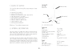
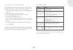
Temperature sensor:
Model:
Resistance NTC (100k
Ω
/R25)
Lead lengths:
Mains connection with shockproof plug approx. 3 metres
Blower connecting lead
approx. 2 metres
Temperature sensor lead
approx. 2 metres
Temperature sensor lead approx. 2 metres:
The flow depends on the resistance of the air system and therefore on the
way the flexible aluminium connecting tubes are installed. The more bends
in the air intake, the greater the resistance encountered by the blower when
forcing the corresponding quantity of air through the system.
That makes it impossible to quote a firm value for the achievable flow in
advance.
Measurements at nominal heat output (11 kW)
• Not in heating mode, at room temperature at blower stage III: 240 m
3
/h
• In heating mode, without blower assistance: 240 m
3
/h
• In heating mode, with blower stage III: 430 m
3
/h
The total of the individual operating states is not reached in heating mode
with the blower because the greater volume flow also increases the resist-
ance in the convection air duct.
3. DESCRIPTION OF FUNCTION
The S-Vent 100 modular forced convection system boosts the natural con-
vection in fireplace inserts with a convection air housing. This system ena-
bles up to 75% more convective heat to be generated and either released
into the room or distributed to other rooms. The system can be used on any
wood-burning fireplace inserts with a square or chamfered convection air
housing. As the convection air housing is left open at the bottom, natural
convection still takes place. Failure of the forced convection system, e.g.
in the event of a power failure or blower fault, will not cause the fireplace
insert to overheat.
4. INSTALLATION INSTRUCTIONS
These installation instructions apply only to the S-Vent 100 modular forced
convection system. The instructions in the fireplace insert installation
manual must be followed when installing the fireplace insert.
Please note:
• The S-Vent 100 modular forced convection system may only be operated
in conjunction with a wood-burning fireplace insert.
• Gas-burning fireplace inserts must not be fitted with the S-Vent 100!
• The maximum ambient temperature for the electronic components
(blower, control unit, etc.) is 60°C.
• The fireplace insert must be provided with a separate combustion air
supply. This is essential to prevent the S-Vent 100 from creating nega-
tive pressure in the room or in the chimney.
• The entire electrical installation of the individual components must be
done by an authorised specialist contractor. All work must be carried
out in accordance with VDE regulations (e.g., VDE 0105, VDE 0116,
VDE 0100, etc.) and the local electricity supplier’s technical connection
conditions.


