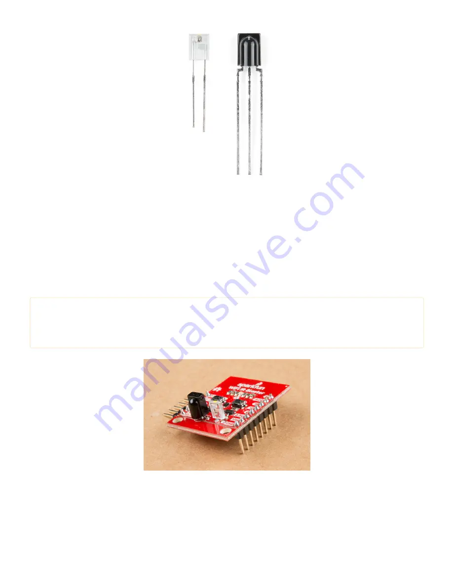
The IR emitter is a Lite-ON LTE-302. It’s driven by an NPN transistor, which helps amplify the current through the
LED.
Assembly Tips
Time to whip out a soldering iron! The IR emitter and receiver do not come soldered onto the WiFi IR Blaster. You’ll
also need to solder headers for programming and power supply pins.
Please note:
Both IR components are polarized -- make sure you solder them in in the correct orientation.
Both components have a bulb-shaped bump protruding from one side, the bumps should both be facing
towards the nearer edge of the board. Silkscreen on the board should also help orient the components.
While you have your iron out, you may also want to solder headers into the 6-pin serial header and the 8-pin
power/GPIO header. Which headers you solder into the board ultimately depends on your application. I like
soldering in a male right-angle header to the 6-pin header, which makes attaching the USB-to-serial board easier.
Straight male headers work well for plugging the board into a bread- or perf-board.
Powering the WiFI IR Blaster


