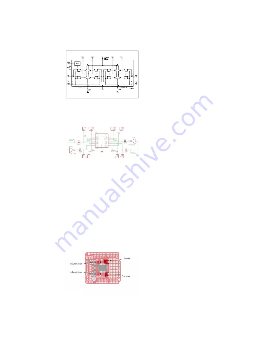
The Ardumoto has been designed primarily to be a motor driver, but we’ve
taken extra time to make sure the L298 IC can be fully controlled, given the
user understands the way it works. The datasheet contains a schematic
diagram of the internal functions of the IC, which is the first thing to look at
and contemplate before trying to do wacky things with your Ardumoto.
A block diagram of the L298 internals from the L298 datasheet
As can be seen from the block diagram, the L298 is actually four totem
drives with two common grounds, intended for full-bridge motor-driving
applications.
A section of the Ardumoto Schematic
To make the Ardumoto, we’ve connected the pairs with one of each
inverted, to allow a direction control. The enable pin is then PWM’d such
that the output goes between drive enabled and high impedance. This
allows coasting of the motors when not driven.
Another way the motors could have been hooked up is to PWM the input
pins and keep enable high. This would provide motor resistance against
movement when not under power, and a PWM value of ½ would be “off.”
Advanced Pins and Connections
The other jumpers and pins are for flexible configuration. They allow the
L298 to be completely isolated from the control lines so that it may be
connected in very specific ways, but it’s up to you to figure out how to solve
the engineering problems you’ll face.
The top side of the Ardumoto
Page 15 of 17


