background image

Page 5

SP-SW5100-VUHD Users Guide

Getting to Know the SP-SW5100-VUHD

Getting to Know the SP-SW5100-VUHD

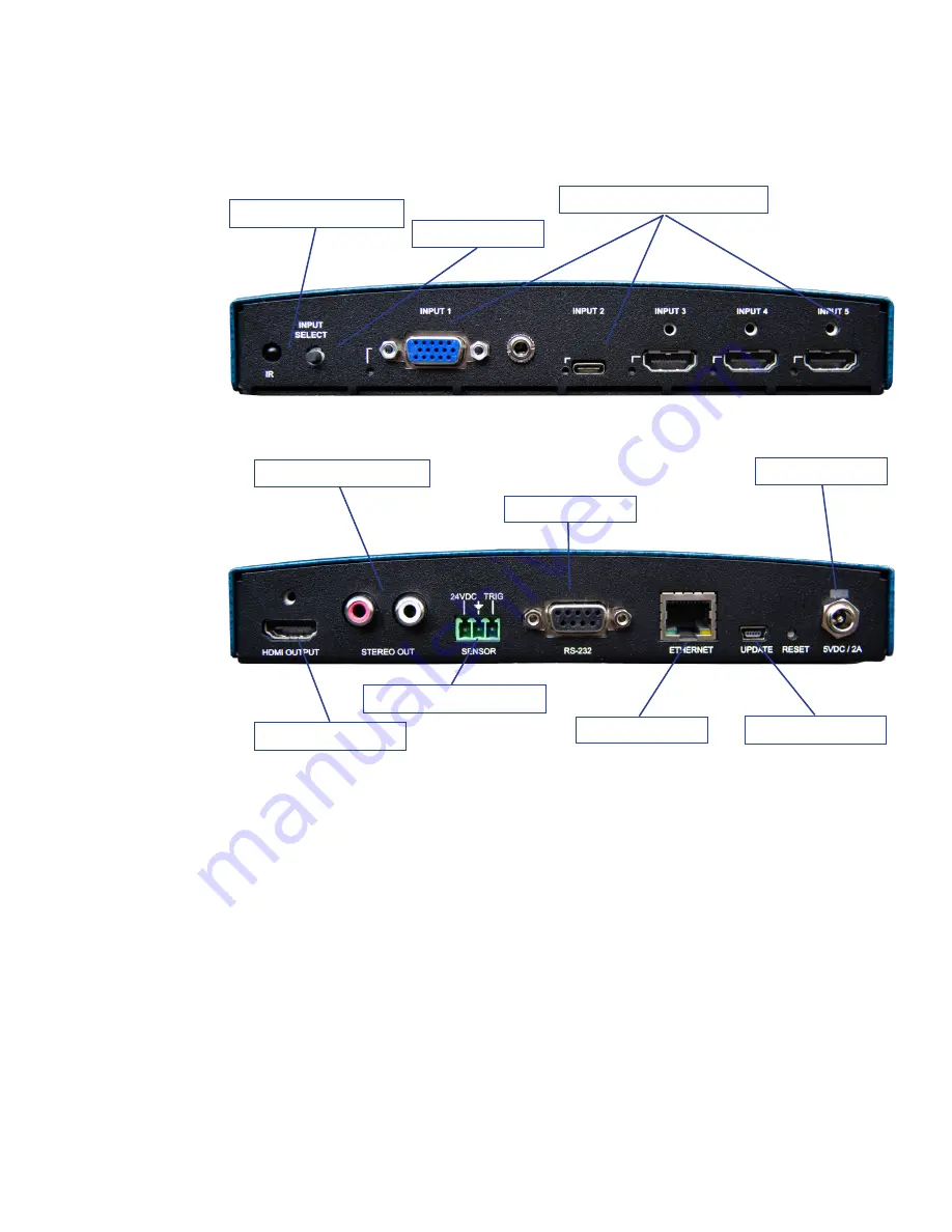
The graphic below points out key attributes of the SP-SW5100-VUHD.

Front View 

Front View 

Back View 

Back View 

Connections

Connections

Device Inputs and Display Outputs

.  Using the graphic above, connect the source devices to 

the ports labeled above as, “Connect Source Devices Here”, and the display at location, “Display 

Output”, port. Connect audio, if applicable.

Amplifier or Powered Speaker Output Connections

.  Connect powered speakers or amplifier to 

the Red and White RCA connectors denoted above as “Stereo Audio Output”.

Control Ports

.  Depending upon your control system, connections can be made to the RS-232 

port, Ethernet port, USB, and/or Proximity Sensor port..

Power

.  Connect the DC power supply to the location, “24VDC”, and the other end to your 

110V/VAC power socket. The system LED will illuminate above “24VDC” location.

Connect Sources Devices Here

IR (Infra-Red) Sensor

Source Selector

Stereo Audio Output

Display Output

USB Firmware Update

Proximity Sensor Port

Power & Indicator

RS-232 Port

Ethernet Port

Summary of Contents for SP-SW5100-VUHD

Page 1: ...Users Guide SP SW5100 VUHD UPDATED April 2020 PN DOC 000032 01a ...

Page 2: ...Stereo Audio Output 7 Volume Control 7 RS 232 Communication Interface 7 RS 232 Port Pinout 8 RS 232 Communication Settings 8 Power 8 Internal Settings 8 Basic Operation 9 Selecting a New Source Device to Display 9 Selecting a New Source Device to Display Using IR Remote 9 How Auto Switching Works 10 Connecting to the Switcher 10 Disconnecting from the Switcher 10 USB Type C Device Connection 10 Co...

Page 3: ...lt 12 Real Time Status Section 13 Terminal Mode View 13 Select Input device to appear on the display 14 Turn Display On Off 14 Change Image Resolution 14 Volume Level 14 Mute Audio 15 Display Control 15 Non Use Timeout 15 Proximity Control 15 LAN Settings 16 Debug Mode 16 Reset 16 Restore System to Factory Defaults 17 ...

Page 4: ... source devices such as a laptop computer and Sony BluRay player to share user supplied content on a single HDMI display such as a high resolution LCD display panel or a LED projector e g output Where audio is included in the video data stream like HDMI DisplayPort USB C etc stereo audio from the selected device is extracted and output on two 2 RCA connectors left right designed for local sound am...

Page 5: ...pplicable Amplifier or Powered Speaker Output Connections Connect powered speakers or amplifier to the Red and White RCA connectors denoted above as Stereo Audio Output Control Ports Depending upon your control system connections can be made to the RS 232 port Ethernet port USB and or Proximity Sensor port Power Connect the DC power supply to the location 24VDC and the other end to your 110V VAC p...

Page 6: ... an HDMI extender By default the SP SW5100 VUHD keeps its display information EDID local to each input There is very little delay from the time an input device asks for the display information to the time the information is sent A device connected to an extender may time out waiting for a response from the display device If a time out occurs the input device will not send its content It is importa...

Page 7: ...ereo Audio Output If external speakers are required connect an RCA cable from the SP SW5100 VUHD Stereo Out connectors to your amplifier or powered speakers The stereo output is the audio extracted from the selected input Volume Control Volume Control Gain levels of the SP SW5100 VUHD stereo output can be adjusted using the IR controller RS232 USB or Ethernet controller Adjustments can also be mad...

Page 8: ...tor to the SP SW5100 VUHD The Power Indicator LED will illuminate above of the 24VDC location to indicate that power is being received Internal Settings Internal Settings In most cases the default settings of the SP SW5100 VUHD are sufficient for most applications However there are times when changes are needed Please contact Tech Support for additional information Further explanation is provided ...

Page 9: ...Output and can be heard on the Stereo Audio Output connectors Note Selecting an input for a source that is not physcially connected will cause the output display to indicate that the signal has been lost or disconnected Selecting a New Source Device to Display Selecting a New Source Device to Display Using IR Remote Using IR Remote From the IR Remote controller shown below select the Right or Left...

Page 10: ...pe C ports Many of these devices such as a Google Chromebook support video out using this port Simultaneously the USB Type C port will accept power if available to charge the laptop or mobile devices Connecting to the Switcher using USB Type C USB C Connecting to the Switcher using USB Type C USB C Connecting a laptop or mobile device using the USB C port is no different than connecting a BluRay p...

Page 11: ...s available on the product web page for the SP SW5100 VUHD And finally it can be adjusted manually using USB USB CDC RS232 and Ethernet terminal emulation menu settings Volume Control using IR Remote Controller Volume Control using IR Remote Controller From the IR Remote controller shown below select the Up and Down buttons until the desired Volume Level is determined One will not see any indicati...

Page 12: ...presentation switchers in real time Connect a Windows based PC to the SP SW5100 VUHD using a USB Type A to USB Micro B cable Windows Mode View default Windows Mode View default This screen view uses standard Windows style menuing to modify the behavior settings of the Switch Switcher Settings App Real Time Status Section Switcher Settings Communications Status ...

Page 13: ...o not have a cable connected or the sources connected is not sending video data VGA 1 is currently selected and sending out a 1920x1080p video stream with a RGB_Limited color format configured for a DVI display Terminal Mode View Terminal Mode View Years ago people used clunky monochrome computer Terminals that were connected to mid size or mainframe computer systems In this mode the system looks ...

Page 14: ...isplay itself has CEC capabilities Change Image Resolution Change Image Resolution To change the resolution we advise the input to use the preferred resolution of the display using a data structure called EDID Extended Display Identification Data The user can change this setting by selecting the EDID Resolution setting as needed To do this select the small down arrow to the right to see the availa...

Page 15: ...m and connects her laptop to the system the display will automatically turn on and her laptop will appear on the screen Non Use Timeout Non Use Timeout When users disconnect their laptops and computers from the presentation the SP SW5100 VUHD will wait this many seconds before the switcher automatically shuts down the display This feature is only applicable when CEC and Display Control is enabled ...

Page 16: ...t to the network Debug Mode Debug Mode This setting is used primarily by in house staff to help a person detect problems in their audio visual system One must use the Terminal Mode to see the messages issued by the debug mode setting Reset Reset By touching the Reset Device button the SP SW5100 VUHD will be reset similar to a person turning off the power and then turning the power back on However ...

Page 17: ... Restore System to Factory Defaults The Factory Def or factory defaults button restores all factory detault settings that were used when the SP SW5100 VUHD was first sent to the customer then performs a software reset However this function does not reset the LAN Settings ...

Page 18: ...antly working to improve the quality of our documentation and we would appreciate your feedback Please send email to sales spcontrols com 2020 Presentation Switchers Inc SP Controls Inc All rights reserved No part of this document may be reproduced or transmitted in any form or by any means electronic or mechanical for any purpose without the express written permission of SP Controls Inc Presentat...

Reviews: