Soyer BMS-10N Operating Instructions Manual Download Page 61

A-3

R

1.3

Adjustment of spring pressure

(does not apply to stud welding pistol PS-3)

When using the stud welding pistol PS-3, adjust the lift instead of the spring
pressure. In this case please leave out chapter 1.3 and refer to chapter 1.4 of
Appendix A "Adjustment of stud welding pistols - Capacitor Discharge".
The pressure with which the stud is pressed against the workpiece during the
welding process is called spring pressure.
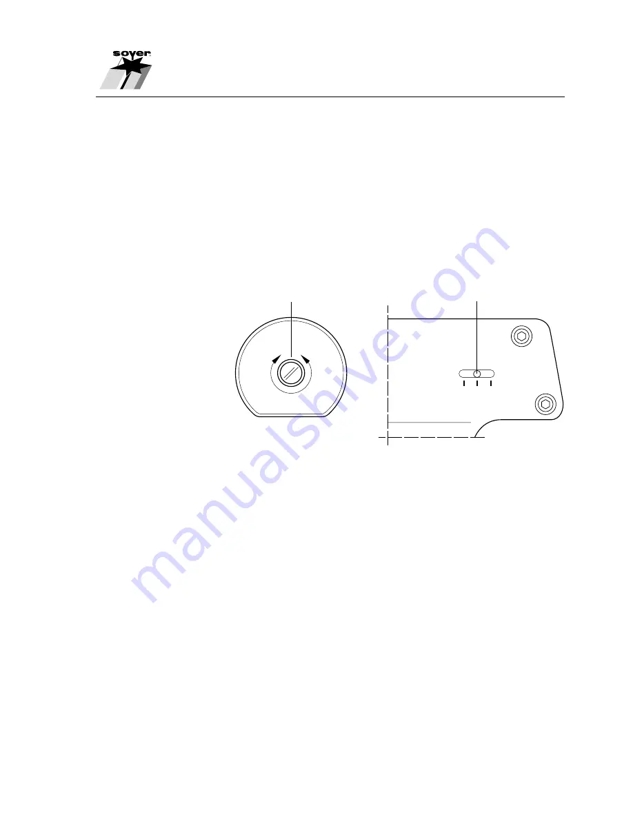
The following illustration shows how to adjust the spring pressure of stud
welding pistol PS-1 which is equipped with a spring pressure indicator. Stud
welding pistol PS-3K is provided with a similar spring pressure indicator. For
stud welding pistols PS-0K and PS-1K, there is no spring pressure indicator.

1 Adjusting screw
2 Spring pressure indicator

For all stud welding pistols described here, the spring pressure is adjusted by
means of the adjusting screw (1). The adjusted pressure is indicated at the
spring pressure scale (2). Adjust spring pressure as follows:

• Turn adjusting screw (1) to the left until stop

Indicator position 1

=

low pressure

• Turn adjusting screw (1) 3.5 turns to the right

Indicator position 2

=

medium pressure

• Turn adjusting screw (1) to the right until stop

Indicator position 3

=

high pressure

The spring pressure to be adjusted depends on the material of both welding
stud and workpiece.

Before starting the work, carry out some experimental weldings and test them
to find out the optimum adjustment.

Samples have to be taken during production to ensure constantly good weld-
ing results (see DVS Guideline 0905, Part 2, "Quality assurance of stud welding
joints").

Appendix A/PS-3 - Adjustment of stud welding pistols - Capacitor Discharge

SZ.0041.E

3 2 1

Spring pressure

2

1

Summary of Contents for BMS-10N

Page 1: ...Operating Instructions Stud Welder BMS 10N BMS 10NV R ...

Page 2: ...h a cross and enter the serial number so that these data are available if you need service support Heinz Soyer Bolzenschweißtechnik GmbH Etterschlag Inninger Straße 14 D 82237 Wörthsee Phone 49 0 81 53 8 85 0 Fax 49 0 81 53 80 30 E Mail verkauf soyer de export soyer de Operating Instructions Stud Welder BMS 10N BMS 10NV ...

Page 3: ...GM registration We have verified that the contents of this pamphlet correspond to the hard and software described Deviations however cannot be excluded so that we cannot warrant for absolute compliance The data in this documenta tion however have been verified regularly and necessary corrections will be incorporated in future impressions We appreciate any suggestions for improvement Heinz Soyer Bo...

Page 4: ...cation of this machine without confirmation shall auto matically annul this declaration Designation of machines Stud Welders with tip ignition Machine type BMS 10N BMS 10NV Machine no 148 Applicable EC directives EC Directive on Machinery 89 392 EEC in the version 91 368 EEC EC Directive on Low Voltage 73 23 EEC EC Directive on Electromagnetic Compatibility 89 336 EEC in the version 93 31 EEC Appl...

Page 5: ......

Page 6: ...R ...

Page 7: ...R ...

Page 8: ...___3 12 3 5 Safety instructions for the operator user _________________________________________________3 12 3 6 The following should be observed before starting the system _____________________________ 3 13 3 7 Before starting welding _____________________________________________________________3 14 3 8 Safety precautions at installation site ____________________________________________________3 1...

Page 9: ...__________________ 7 30 8 Maintenance _____________________________________________________________________ 8 31 8 1 Stud welder ________________________________________________________________________ 8 31 8 2 Replacement of components __________________________________________________________8 31 9 Troubleshooting __________________________________________________________________ 9 32 10 Transpo...

Page 10: ...____________________________A 4 1 4 2 Adjusting the lift ______________________________________________________________________A 5 2 Initiation __________________________________________________________________________ A 6 2 1 Total view ___________________________________________________________________________A 6 2 2 Connecting the stud welding pistols to the stud welder ________________________...

Page 11: ...ate the stud welder ᏘMORTAL DANGER Persons with pacemakers must not operate the stud welder and must not stay in the vicinity of the stud welder while it is running Ensure that the stud welder is not operated near electronically sensitive life supporting equipment such as in intensive care units in hospitals WARNING Keep sufficient distance from electronic devices When stud welding highly intensiv...

Page 12: ...formations so that even thin sheet metals under 1 mm sheet thickness retain their decorative appearance If you need advice or assistance in solving problems please contact either our parent company or our field engineers 1 3 Information on the product Manufacturer Heinz Soyer Bolzenschweißtechnik GmbH Etterschlag Inninger Straße 14 D 82237 Wörthsee Phone 49 0 81 53 8 85 0 Fax 49 0 81 53 80 30 E Ma...

Page 13: ...nder normal conditions and comprise the following chapters in detail Chapter 1 General Information on application and product as well as supplementary informa tion Chapter 2 Description of stud welder Description of tip ignition technology and of the stud welder Chapter 3 Safety instructions All safety regulations which are relevant with regard to installation and operation of the stud welding sys...

Page 14: ...raining operate the system 1 5 3 Conduct in the case of malfunctions If malfunctions occur first try to detect and eliminate the causes according to the list in chapter 9 Troubleshooting of our operating instructions In all other cases contact our service department Important information If you require our service please make sure that you supply us with the if service is required following inform...

Page 15: ...milliseconds 0 001 0 003 sec 2 2 Stud welder set up The standard pistol to be connected to the stud welders BMS 10N and BMS 10NV is the stud welding pistol PS 3 with control cable The stud welders are optionally equipped with an automatic module for the connection of the univer sal feeder UVR 250S and for fully automatic stud feed It is necessary to use the stud welding pistol PS 3A or the welding...

Page 16: ...rs BMS 10N and BMS 10NV have a robust handy and compact design and identical dimensions SZ 0045 E 0 1 AT 10 AT HAUPTSCHALTER I 0 Φ 000 R BMS 10N Heinz Soyer Bolzenschweißtechnik GmbH Etterschlag Inninger Str 14 82237 Wörthsee Tel 08153 885 0 Depth 380 mm 400 220 ...

Page 17: ...and brass depending on requirements Tip ignition as per DVS Leaflet 0903 with gap and contact welding Stud welding pistol PS 3 Capacitor battery 88 000 µF 50 200 V infinitely variable up down 0 001 0 003 sec up to 20 studs min depending on stud diameter 220 230 V 50 60 Hz 10 AT 10 special voltage on request 0 1 AT for main switch 10 AT for control transformer 3 m highly flexible 2 x 3 m highly fle...

Page 18: ... Block diagram SZ 0067 E Pistol Earth Automatic module N 88mF NV 132mF Ventilator Control board STA 31 Control board STA 41 Mains transformer Supply 115 230V Mains filter Mains switch 10AT 0 1AT Pistol control cable Feeder CNC Interfaces ...

Page 19: ...ontrol 1 2 3 4 5 6 7 8 9 Start Start SOW Release 9 pole D Sub socket terminal strip Terminology Start SOW Ready Reload Contact releases the welding process Stud on workpiece Is only required when stud welder is operated via a superior control Contact is made when stud touches the workpiece e g head in fore position Contact is made after the set charging voltage has been reached Contact remains clo...

Page 20: ...escription of stud welder 2 7 Alteration of supply voltage SZ 0069 E Mains supply Line Mains supply Line violet violet black black grey or white orange grey or white orange Binding post Supply 230V Supply 115V ...

Page 21: ... high temperatures voltages etc listed under the other main items have to be complied with 3 1 Description of reference signs in the operating instructions The non observance of safety instructions can cause damage to persons The safety instructions of this manual are marked with the general symbol for danger safety symbol in compliance with DIN 4844 W9 Warning of electric voltage is specially mar...

Page 22: ...he appropriate training courses for your personnel 3 3 Dangers in the case of non compliance with safety instructions The non compliance with safety instructions may not only endanger persons but also the welding system and its environment Any non compliance with safety instructions may result in a complete loss of damage claims Non compliance with safety instructions may have the following conse ...

Page 23: ... use of the system by children or unqualified personnel Wear non combustible closed working clothes Wear a leather apron to protect your clothes from welding spatters that are generated during the welding process Wear a head protection when carrying out welding works above your head MORTAL DANGER When welding do not wear clothes soiled with easily combustible substances such as oil grease and para...

Page 24: ...Make sure room is well ventilated or extract welding fumes if necessary DANGER TO HEALTH When welding fumes and suspended matters may be generated Beware of fumes detrimental to health particularly when using surface treated materials If possible only weld in rooms which are higher than 3 m As per VBG 15 special regulations are applicable for narrow rooms 3 9 Working with the stud welder Comply wi...

Page 25: ...1 Unauthorized retrofit and spare parts production The system may only be retrofitted and modified after consultation with the manufacturer Original spare parts and accessories authorized by the manufac turer guarantee safety The use of other parts may result in the cancellation of warranty for any consequences thus caused 3 12 Inadmissible operating methods Limit values Working safety of the stud...

Page 26: ... off valve of the compressed air supply Activate the pistol switch several times until the pressure in the lines drops completely Disconnect the compressed air supply connections at the rear side item 18 and 19 chapter 5 1 and at the front side item 8 and 9 chapter 5 1 Disconnect the interface plug from the connecting socket item 14 chapter 5 1 at the rear side of the stud welder Disconnect the pl...

Page 27: ...istant to environmental influences it should be protected against dampness and dust This is easily achieved by placing the welding system on a workbench Please pay particular attention to the bearing strength of the workshop furniture and a safe and stable position Make sure there is sufficient free space around the air apertures Install the stud welder close to the welding location Observe the co...

Page 28: ...er Bolzenschweißtechnik GmbH Etterschlag Inninger Str 14 82237 Wörthsee Tel 08153 885 0 Front view 1 Fuse element with fuse 0 1 AT 2 Main switch 3 Fuse element with fuse 10 AT 4 Energy range controller 5 Charging voltage display 6 Function key Lift adjustment 7 LED displays 8 Air function forward optional 9 Air function backward optional 10 Control cable socket 11 Welding cable socket 12 Earth cab...

Page 29: ...rry out function tests without welding current for welding pistols and heads lift test and to adjust the lift At the rear side of the stud welder a welding quantity counter is installed to record the welding quantities The standard CNC interface allows a problem free connection of the stud welder to bench welders Short charging cycles and high reserve capacities guarantee the readiness for operati...

Page 30: ... The digital display shows the adjusted energy value charging voltage in volts LED displays item 7 chapter 5 1 The LEDs show the respective operational states 5 2 3 Connecting elements Mains connecting cable item 13 chapter 5 1 Use the mains connecting cable to connect the stud welder to the power supply Earth cable connectors item 12 chapter 5 1 The earth cable connectors allow the earth terminal...

Page 31: ...ion for welding pistols or heads with automatic stud feed 5 2 4 Fuse Fuse item 1 and 3 chapter 5 1 The stud welder is protected by two fuses 0 1 AT and 10 AT WARNING If you have to replace fuses only use those with specified electrical values Oversized fuses could either cause defects to the electrical system or a fire Ꮨ Disconnect the mains plug from the power supply when replacing fuses ...

Page 32: ...t LED lights up when lifting magnet of welding pistol is activated LED Ready LED lights up when stud welder is ready for operation LED Stud on Workpiece LED lights up when earth pole is connected and the stud touches the workpiece LED Release LED lights up when trigger switch of welding pistol or head is pressed Earth Marks earth cable connectors to be connected with earth cables Pistol Marks cont...

Page 33: ...ute of both earth clamps This guarantees a current distribution around the stud that is balanced to the largest possible extent and satisfactory welding results Difficult areas are welds on the edge of the workpiece or greater non homogeneities in material thickness i e the sheet thickness varies by a few millimeters or additional material is welded or riveted to the metal This also includes stud ...

Page 34: ...or welding heads with magnet e g PS 3 PS 3A The lift on the stud welding pistol or welding head is adjusted as follows Switch on main switch item 2 chapter 5 1 Press function key Lift adjustment item 6 chapter 5 1 The LED Lift item 7 1 chapter 5 2 2 lights up Charging voltage returns to 0 Position pistol on workpiece Press pistol switch Stud holder lifts off the workpiece and lift can be ad justed...

Page 35: ... increased too Random samples should be taken during any production process to ensure constantly good welding results see DVS Guideline Part 1 Quality assurance of stud welding joints The welding parameters were determined with the stud welder BMS 10N and the stud welding pistol PS 3 using a lift adjustment of about 2 5 mm A steel plate with a thickness of 2 mm served as base metal for welding cop...

Page 36: ... 2 0 0 0 0 2 2 1 0 0 0 Ws 1 4303 stainless or similar St 36 2 CuZn 37 Ms63 AlMg 3 AlSi 12 Al 99 5 CrNi steels austenitic CuZn 37 CuZn 30 Ms 63 70 without lead Copper Al 99 99 5 AlMg 3 AlMg 5 AlMgMn AlMgSi 0 5 AlMgSi 1 AlSi 5 2 1 2 0 0 0 2 2 1 0 0 0 2 2 1 0 0 0 0 0 0 1 1 1 0 0 0 1 1 1 0 0 0 2 1 1 1 well suited 2 sufficiently suited depending on requirements 0 not suited SZ 0049 E ...

Page 37: ...ivate pistol switch LED Release item 7 4 chapter 5 2 2 lights up and welding process is started Charging voltage returns to 0 LED Stud on workpiece item 7 3 chapter 5 2 2 lights up LED Ready item 7 2 chapter 5 2 2 goes out Stud welder is not ready for welding Remove pistol from the workpiece All LEDs go out and the stud welder is charged to the set value After the value has been obtained LED Ready...

Page 38: ...f of qualification for working with stud welding equipment see DVS Guideline 0905 part 2 sections 4 1 and 4 2 The proof of qualification applies in particular to the fastening of structures that are relevant in terms of safety regulations When being used in the building industry only approved base and stud materials may be used for example see DIN 4100 section 2 1 certificate of approval for stain...

Page 39: ...he component to be welded later If it is possible and sensible from an economical point of view use parts that are identical to those used in later production 7 5 2 Visual inspection The visual inspection serves as a rough check for major defects The uniformity of the weld is assessed When in doubt tensile and bend tests should be carried out 7 5 3 Tensile test The tensile test serves to test the ...

Page 40: ...s selected The welding zone is subjected to undefined tension pressure and bending A minimum of 3 studs is welded and bent to an angle of 30 by means of a tube that is slipped over the stud The test is considered as suc cessful if no superficial fissure or fracture is detected in the welding zone The acceptance number in accordance with DIN 267 part 5 as per AQL 4 must be complied with If the quan...

Page 41: ...er supply and the compressed air supply from the stud welder connections Unscrew recessed head screws at both side parts Remove upper part of the housing by lifting it vertically from the unit please pay attention to the earth connection Blow through the interior of the stud welder using clean dry and filtered compressed air with a pressure of about 2 bar If no compressed air is available a vacuum...

Page 42: ...elecommunication data please refer to chapter 1 6 page 1 4 Ꮨ MORTAL DANGER Always disconnect the connecting plug from the socket before opening the housing of the stud welder Only trained and appropriately qualified person nel are allowed to open the housing and to carry out works on the electric power supply and stud welder DANGER OF ACCIDENTS Only trained and appropriately qualified personnel ar...

Page 43: ...centre mark Control of stud welder or welding pistol is defective Contact SOYER customer service Stud is too loose in stud holder Press stud holder together or tighten it Stud thread is scorched Stud holder is worn Replace stud holder Varying welding results Welding energy not correctly set Set welding energy Cable connections are too loose Transition resistances are generated Check all cable conn...

Page 44: ...deformed Use new welding studs Stud projection over stud holder incorrectly set Set projection to 2 3 mm set distance between stud holder and stud weld base Spring pressure incorrectly set Set spring pressure Welding pistol in tilted position Ensure that all 3 pistol legs are simultaneously and evenly positioned on the workpiece Stud welder switches itself off There are mains voltage fluctuations ...

Page 45: ...s These carrying handles are intended for transport by hand only Never pull ropes through these handles to lift the system by crane to the installation site The system would become unstable and might tilt from its original position As a result the handles could rip and the system fall on the ground DANGER TO HEALTH Prevent unauthorized use of the stud welding system by children and unqualified per...

Page 46: ... VDE 0544 Safety requirements for arc welding equip ment VGB 1 General instructions instructions for accident prevention VBG 5 Power operated substances instructions for accident prevention DIN 4100 Welded steel structures with predominantly dead load DIN 267 part 5 Screws nuts and the like technical terms of delivery testing and acceptance DIN 17100 Constructional steels general types quality sta...

Page 47: ...ery Any claim to a warranty will be forfeited if damages are caused by improper operation or if repairs or interferences have been made by unauthorized personnel or whenever accessories and spare parts have been used which do not match our equipment We cannot guarantee the quality of welded joints if welding studs acquired from another company are used ...

Page 48: ...or BMS 10N stud welder Overview Item No Quantity Description Order No 1 22 Cap PVC grey M01251 2 22 Fillister head screw M4x10 M01254 3 22 U washer M4 nylon M01251 01 4 1 Upper part of housing of BMS 10N F03598 5 2 Handle M01240 6 4 Tooth lock washer M8 M01224 ...

Page 49: ...13 39 Spare parts R 13 2 Exploded view of BMS 10N stud welder Overview D E C A B F SZ 0166 X 1 2 3 4 5 6 ...

Page 50: ...size M6 M01707 17 1 Toroidal mains transformer BV 47718 E03537 18 4 Hexagon nut M4 M01012 19 4 Spring ring M4 M01074 20 1 Connecting cable for pulse counter F03707 FA E 21 1 Complete flat cable 26 pole F03617 FA E 22 1 Fine wire fuse 10AT E01898 23 1 Fine wire fuse 1 6AT E03608 24 1 Fine wire fuse 3 15 AT E01895 25 1 PC Board STA 41 F03630 FA 26 2 Hexagon nut M4 M01012 27 1 Complete flat cable F03...

Page 51: ...13 41 Spare parts R 13 4 Exploded view of BMS 10N stud welder View A A SZ 0167 X 1 2 3 4 5 6 7 8 9 11 11 10 7 13 14 15 16 17 12 18 19 20 21 22 23 24 25 26 27 28 29 30 31 32 33 34 35 36 37 38 39 ...

Page 52: ... 2 Hexagon nut M4 M01012 16 2 Spring ring M4 M01074 17 8 Spring ring M5 M01075 18 8 Hexagon head cap screw M5x12 M01117 19 4 Hexagon nut M4 M01012 20 4 Spring ring M4 M01074 20 1 4 Nylon washer E03728 20 2 4 Insulating disk E02037 21 1 Busbar left F01299 22 1 Busbar middle F01301 23 1 Busbar right F01300 24 3 Hexagon nut M8 M01015 25 3 Spring ring M8 M01077 26 3 Washer M8 M01065 27 1 Connecting ca...

Page 53: ...13 43 Spare parts R 13 6 Exploded view of BMS 10N stud welder View B and C B C SZ 0168 X 1 2 3 4 5 6 7 8 9 10 11 12 13 14 15 16 17 18 19 20 20 1 20 2 21 22 23 24 25 26 27 28 29 31 32 30 33 34 35 36 ...

Page 54: ...n board M02101 15 1 Pneumatic valve M02099 16 2 Tooth lock washer M3 M01318 17 2 Hexagon nut M3 M01011 18 2 Angular joining piece M5 PU 3 M01056 19 2m Pneumatic hose SMC4 M01067 20 1 Joining piece QM 1 4 M01290 21 1 Sound absorber U 1 8 M01285 22 1 Reducer M01538 23 1 Elbow PU 4 M03518 24 1 Pneumatic valve M02098 25 1 Pin and socket connector straight KQH 06 M02095 26 4 Washer M4 M01062 27 4 Sprin...

Page 55: ...13 45 Spare parts R 13 8 Exploded view of BMS 10N stud welder View D and E D E SZ 0169 X 1 2 3 4 5 6 7 8 9 10 11 12 13 14 15 16 17 18 19 20 21 22 23 24 25 26 27 28 29 30 31 32 33 34 35 36 37 ...

Page 56: ...plete turning knob comprising 1 Turning knob E01900 1 Nut cover E01902 1 Front cap E01904 21 2 Earth connector E01964 22 1 Earth socket E01958 23 2 Pin and socket connector straight M01060 24 1 Fine wire fuse 0 1AT E03504 25 1 Fine wire fuse 10AT E01898 26 2 Locking screw E01891 27 2 Coupler socket KD 1 8 M01299 28 1 Copper plate F03529 29 2 Hexagon nut M8 M01015 30 2 Spring ring M8 M01077 31 2 Wa...

Page 57: ...47 Spare parts R 13 10 Exploded view of BMS 10N stud welder View F Hau F SZ 0170 X 1 2 3 4 5 8 11 12 10 13 14 15 16 17 19 18 20 21 22 23 24 25 26 27 28 29 30 31 32 33 34 34 1 35 36 37 38 39 40 41 42 43 44 ...

Page 58: ...13 48 Spare parts R ...

Page 59: ...h does not exceed 35 mm 1 Stud 3 Counternut 2 Stud holder 4 Stop screw For different stud diameters different stud holders are required Adjust stud holder as follows Loosen counternut 3 Insert stud 1 into stud holder The top edge of the stud flange must project for about 1 5 mm from the front edge of the stud holder The stud must make contact with the stop screw 4 Adjust stop screw 4 in the stud h...

Page 60: ...eve nut 3 at stud welding pistol PS 1 PS 3 and PS 3K by means of socket wrench SW 17 those at stud welding pistols PS 0K and PS 1K by means of socket wrench SW 14 Insert stud holder 2 into spring piston 5 until stop Tighten stud holder 2 with sleeve nut 3 The stud flange must project from the top of the pistol legs or the support tube for the thickness of the flange If this is not the case remove ...

Page 61: ... Spring pressure indicator For all stud welding pistols described here the spring pressure is adjusted by means of the adjusting screw 1 The adjusted pressure is indicated at the spring pressure scale 2 Adjust spring pressure as follows Turn adjusting screw 1 to the left until stop Indicator position 1 low pressure Turn adjusting screw 1 3 5 turns to the right Indicator position 2 medium pressure ...

Page 62: ...welder Position welding pistol with welding stud chapter 1 4 1 item 6 on workpiece chapter 1 4 1 item 7 Press pistol switch Stud holder chapter 1 4 1 item 4 with welding stud chapter 1 4 1 item 6 is lifted off workpiece chapter 1 4 1 item 7 Depending on the respective welding task the stud should lift off the workpiece for 2 5 4 mm Appendix A PS 3 Adjustment of stud welding pistols Capacitor Disch...

Page 63: ...turning to the left or right till the required lift is obtained Turning to the left increases the height of lift turning to the right decreases it After adjusting check the lift and correct it if necessary After having adjusted the lift fix it by means of the setscrew 3 Tighten setscrew 3 by turning it clockwise using Allen key SW 2 Terminate the function Lift test after having successfully adjust...

Page 64: ...tud welding pistols PS 0K and PS 1K are not equipped with a spring pressure indicator Stud welding pistol PS 3 is equipped with a lift indicator and adjusting screw for lift instead of the spring pressure indicator chapter 2 1 item 3 and adjusting screw for spring pressure chapter 2 1 item 4 1 Sleeve nut 4 Adjusting screw for 2 Pistol leg spring pressure or lift 3 Spring pressure indicator stud we...

Page 65: ...tol and control cables 2 3 Operation Connect stud welder to earth Connect stud welding pistol as described in chapter 5 Adjust stud welding pistol as described in Appendix A Chapter 1 Connect stud welder to the mains supply Adjust stud welder for the welding studs to be used Insert welding studs into stud holder Place stud welding pistol upon workpiece and press trigger switch ...

Page 66: ...A 8 R Appendix A PS 3 Spare parts Capacitor Discharge 3 Spare parts 3 1 Spare parts list for PS 3 stud welding pistol Spare parts list in preparation ...

Page 67: ...A 9 R Appendix A PS 3 Spare parts Capacitor Discharge Spare parts list in preparation 3 2 Exploded view of PS 3 stud welding pistol ...

Page 68: ...A 10 R Appendix A PS 3 Spare parts Capacitor Discharge ...

Page 69: ...einz Soyer Bolzenschweißtechnik GmbH Etterschlag Inninger Straße 14 D 82237 Wörthsee Tel 49 0 81 53 8 85 0 Fax 49 0 81 53 80 30 Internet www soyer de www soyer com E Mail verkauf soyer de export soyer de ...

Reviews: