-24-
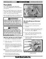
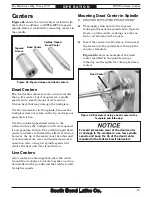
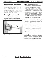
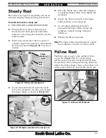
For Machines Mfg. Since 7/09
EVS Toolroom Lathes
O P E R A T I O N
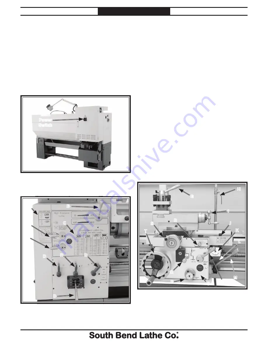
Refer to the following figures and descriptions
to become familiar with the basic controls of this
machine.
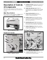
Main Power Switch
The main power switch is shown in
Figure 33
. It
turns master power
ON/OFF
to the lathe.
A. Change Gear Chart:
Displays the positions of
the various gears for different threading or
turning options.
B. Spindle Speed Range Lever:
Shifts the
headstock into low or high range for spindle
speeds between 20–400 RPM or 400–2500
RPM.
C. Thread and Feed Chart:
Shows the
configurations of the gearbox levers to
achieve a particular feed rate.
D. Gearbox
Levers:
Move the gearbox gears
into particular ratios, which then turn the
leadscrew and feed rod for threading and
power feed operations.
E. Feed Direction Lever:
Shifts the direction
that the gearbox is turning, which changes
the direction of the leadscrew and feed rod.
F.
Gearbox Range Lever:
Shifts the gearbox
between high, neutral, or low range and has
no effect on spindle RPM.
G. 4-Position Tool Post Lever:
Locks the rotary
tool post in four possible detents.
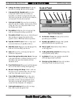
Carriage Controls
G
T
N
M
Q
R
S
I
P
H
Figure 35. Carriage controls.
O
K
L
J
Figure 33. Main power switch.
Main
Power
Switch
Headstock Controls
D
D
D
A
D
C
B
Figure 34. Headstock controls.
E
F
Description of Controls
& Components

