background image

For Machines Mfg. Since 8/11

Model SB1001 8K

 Lathe

-65-

P A R T S

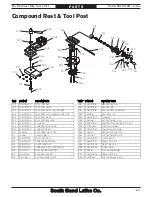
Compound Rest & Tool Post

REF PART #

DESCRIPTION

REF PART #

DESCRIPTION

301

PSB1001301

TOOL POST NUT

319

PSB1001319

GRADUATED DIAL

302

PSB1001302

TOOL POST LEVER

320

PSB1001219

HANDLE HUB

303

PSB1001303

TOOL POST BODY FLAT WASHER

321

PSB1001218

BALL HANDLE ASSEMBLY

304

PSB1001304

TOOL POST CAP SCREW M8-1.25 X 30

322

PRP02M

ROLL PIN 3 X 16

305

PSB1001305

TOOL POST BODY

323

PSB1001307

PLUNGER

306

PSB1001306

TOOL POST BUSHING

324

PSS26M

SET SCREW M5-.8 X 6

307

PSB1001307

PLUNGER

325

PSB1001221

COMPRESSION SPRING 0.5 X 4 X 7

308

PSB1001308

COMPRESSION SPRING

326

PSTB004M

STEEL BALL 5MM

309

PSB1001309

COMPOUND REST

327

PSB1001327

COMPOUND REST GIB

310

PSS57M

SET SCREW M5-.8 X 20

328

PN46M

HEX NUT M8-1.25 THIN

311

PN06M

HEX NUT M5-.8

329

PCAP10M

CAP SCREW M5-.8 X 15

312

PSB1001312

TOOL POST BOLT

330

PSB1001330

CLAMP BASE

313

PSB1001313

COMPOUND REST WAY

331

PSB1001331

DOWEL PIN 3 X 18

314

PSB1001314

LEADSCREW NUT

332

PSB1001332

T-BOLT M8-1.25

315

PSB1001315

COMPOUND REST LEADSCREW

333

PSB1001333

CLAMP RING

316

P6800ZZ

BALL BEARING 6800ZZ

334

PW02M

FLAT WASHER 5MM

317

PSB1001317

BEARING HOUSING

335

PSB1001335

DOWEL PIN 3 X 12

318

PCAP10M

CAP SCREW M5-.8 X 15

336

PCAP33M

CAP SCREW M5-.8 X 12

301

302

303

304

305

306

307

308

309

310

311

312

313

314

315

316

316

317

318

319

320

321

322

323

324

325

326

327

328

329

336

330

331

332

333

334

335

Summary of Contents for 8K SB1001

Page 1: ...Copyright December 2011 For Machines Mfg Since 8 11 MODEL SB1001 8K 8 X 18 VARIABLE SPEED LATHE OWNER S MANUAL...

Page 2: ...n is a process that happens through training and experience If you are not an experienced operator of this type of machinery read through this entire manual then learn more from an experienced operato...

Page 3: ...dle Break In 23 Recommended Adjustments 23 OPERATION 24 Operation Overview 24 Chuck Faceplate Mounting 25 Chuck Installation 25 Chuck Removal 27 Scroll Chuck Clamping 27 4 Jaw Chuck 28 Mounting Workpi...

Page 4: ...Storage 53 Leadscrew End Play Adjustment 53 Gib Adjustment 54 Saddle Gib 54 Cross Slide Compound Rest Gibs 55 Adjusting Drive Belts 55 TROUBLESHOOTING 57 ELECTRICAL 59 Electrical Safety Instructions...

Page 5: ...We appreciate your business and hope this machine serves you well for a lifetime 8K Lathe Dating back to 1931 the first South Bend 8 Bench Lathe made it much easier for machinists around the world to...

Page 6: ...users have an increased risk of seriously injuring themselves with this machine Do not operate this machine until you have understood this entire manual and received proper training Control Panel Ele...

Page 7: ...ual before beginning any lathe operations Control Panel Figure 1 Master power switch location Master Power Switch A Spindle Speed Dial Controls the variable spindle speed B Emergency STOP Button Cuts...

Page 8: ...specific inch thread pitches I Half Nut Lever Engages disengages the half nut for threading operations J Carriage Handwheel Moves the carriage along the bedway K Cross Slide Ball Handle Moves the cros...

Page 9: ...ne Weight 313 lbs Length x Width x Height 44 x 21 x 24 in Must Ship Upright N A Electrical Power Requirement 120V Single Phase 60 Hz Prewired Voltage 120V Full Load Current Rating 10A Minimum Circuit...

Page 10: ...rings High Precision Tapered Roller Tailstock Info Tailstock Quill Travel 1 3 4 in Tailstock Taper MT 2 Tailstock Barrel Diameter 1 1875 in Threading Info Number of Longitudinal Feeds 9 Range of Longi...

Page 11: ...lows Death or catastrophic harm WILL occur Moderate injury or fire MAY occur Death or catastrophic harm COULD occur Machine or property damage may occur Basic Machine Safety Owner s Manual All machine...

Page 12: ...verifying that all fastening devices are properly secured and items attached to spindles have enough clearance to safely rotate Chuck Keys or Adjusting Tools Tools used to adjust spindles chucks or a...

Page 13: ...g hazard To decrease your risk change coolant regularly and position the nozzle where it will not splash or end up on the floor Clearing Chips Metal chips can easily cut bare skin even through a piece...

Page 14: ...h deadly force To reduce the risk of this hazard read and understand this document and seek additional training from an experienced chuck user before using a chuck Chuck Capacity Avoid exceeding the c...

Page 15: ...workbench or stand 5 Assemble the loose components and make any necessary adjustments or inspections to ensure the lathe is ready for operation 6 Check lubricate the lathe 7 Connect the lathe to the p...

Page 16: ...that the machine will draw If the machine is overloaded it will draw additional amps beyond the full load rating If the machine is overloaded for a sufficient length of time damage overheating or fir...

Page 17: ...m Length Shorter is Better 50 ft This machine must be grounded In the event of certain types of malfunctions or breakdowns grounding provides a path of least resistance for electric current in order t...

Page 18: ...Timing Belt Pulley 22T 1 G Timing Belt Pulley 21T 1 H Timing Belt Pulley 20T 1 I Timing Belt Pulley 19T 1 J Timing Belt Pulley 18T 1 K Timing Belt Pulley 16T 1 L Timing Belt Pulley 38T 1 M Timing Belt...

Page 19: ...rface to make sure they will not damage it Basic steps for removing rust preventative 1 Put on safety glasses and disposable gloves 2 Coat all surfaces that have rust preventative with a liberal amoun...

Page 20: ...ll be used Additionally consider the weight of the operator and any dynamic loading that may occur when operating the machine Physical Environment The physical environment where your machine is operat...

Page 21: ...reduce the risk of a lifting or dropping injury ask others for help Mounting The base of this lathe has mounting four holes that allow it to be secured to a workbench or stand to prevent it from movi...

Page 22: ...ave completed all previous preparation instructions and power supply requirements the machine is ready to be connected to the power supply To avoid unexpected startups or property damage use the follo...

Page 23: ...igure 14 on the front of the machine is turned OFF 2 Read and follow the safety instructions at the beginning of the manual take all required safety precautions and make sure all previous preparation...

Page 24: ...or correcting potential problems 12 Use the spindle speed dial to increase and decrease spindle speed to verify the operation of the dial 13 Move the spindle switch to the OFF position let the spindle...

Page 25: ...and move the spindle switch to the middle OFF position 4 When the spindle has come to a complete stop move the spindle switch to the right position and run the spindle in reverse at 2300 RPM for anoth...

Page 26: ...g into the workpiece 9 When finished cutting moves the spindle switch to the OFF middle position waits until the spindle is completely stopped then removes the workpiece To reduce the risk of serious...

Page 27: ...ks that are adjusted with an 8mm hex wrench to securely mount a chuck or faceplate with repeatable precision and ease Never use spindle speeds faster than the chuck RPM rating or the safe limits of yo...

Page 28: ...7 When the chuck is fully seated and all the camlocks are tight verify that the chuck fits the spindle properly by checking for any gaps between the mating surfaces If there are no gaps proceed to St...

Page 29: ...slide the studs out of the cam holes If the chuck does not immediately come off rotate it approximately 60 and tap it again Make sure all the marks on the cams and spindle are in proper alignment for...

Page 30: ...a sturdy piece of plywood under the spindle to protect the bed ways during the installation process 3 Use the chuck key to open each jaw so the workpiece will lay flat against the chuck face jaw steps...

Page 31: ...f THREE independent clamping devices to hold the workpiece onto the faceplate Failure to properly secure a workpiece to the faceplate could cause it to be thrown from the lathe with deadly force at th...

Page 32: ...r see Figures 27 for examples If the arbor has an open hole in the end a screw can be threaded into the end of it to provide a solid surface for the quill pin to push against when the quill is retract...

Page 33: ...ther to move the tailstock top casting in the desired direction see the illustration in Figure 29 3 Make sure both offset set screws are snug then re tighten the tailstock lock nut to secure the offse...

Page 34: ...ure 31 Example photo of stock mounted between the centers 6 Turn 0 010 off the stock diameter 7 Mount a dial indicator so that the plunger is on the tailstock quill 8 Use calipers to measure both ends...

Page 35: ...uded for mounting the MT 3 center in the spindle Figure 34 Tapered spindle sleeve and dead centers Adapter Sleeve MT 3 Center MT 2 Center Figure 35 Example of a live center SB1241 MT 2 Live Center sho...

Page 36: ...ep the tip of the dead center mounted in the tailstock well lubricated Mounting Center in Tailstock Either a carbide tipped dead center or live center can be used in the tailstock Mounting instruction...

Page 37: ...may become difficult to remove later and the excess pressure will result in unnecessary friction and heat which may damage the workpiece and center Figure 38 Example photo of a workpiece mounted betwe...

Page 38: ...14mm 1 To set the compound rest at a certain angle 1 Loosen the two hex nuts at the base of the compound rest 1 of 2 shown in Figure 41 Compound Rest Figure 41 Compound rest Compound Rest Hex Nut 1 o...

Page 39: ...ck To Spindle Centerline on Page 31 for detailed instructions Make a facing cut on a piece of round bar stock If the tool is above or below the spindle centerline a nub will be left in the center of t...

Page 40: ...l need to 1 Determine the best spindle speed for the cutting task and 2 configure the lathe controls to produce the required spindle speed Determining Spindle Speed Many variables affect the optimum s...

Page 41: ...ONNECT LATHE FROM POWER 2 Open the end cover 3 Loosen the pivot block hex nut see Figure 49 This will allow the tensioning bolt to change the position of the idler pulley in the next step 4 Turn the t...

Page 42: ...by rotating the spindle speed dial see Figure 51 until the tachometer display shows the desired spindle speed Figure 51 Spindle speed controls Spindle Speed Dial Tachometer Display Power Feed Threadi...

Page 43: ...in Feed Rate of 0 0041 rev Pulley Identification 6 Arrange the timing belts and pulleys as indicated in the illustration above the feed rate chart see Figures 56 57 and the pulley identification colum...

Page 44: ...sive wear and stretching Adjusting the tension too loosely could cause the belt to slip during operation 9 Close the end cover before re connecting the lathe to power Setting Threading Controls Using...

Page 45: ...timing belts in positions E and F 7 Apply pressure to the upper right pulley as you re tighten the shaft hex nut on that pulley shaft 8 Continue to apply pressure on the pulley as you re tighten the...

Page 46: ...or 32 TPI For each of these thread pitches use any line on the thread dial see Figure 65 Figure 65 Any line on the dial for threading 16 24 or 32 TPI 2 2 2 4 4 4 Any Position 16 24 32 Any Numbered Pos...

Page 47: ...disengage the leadscrew and end pulleys from the drive train a Back out the tensioning thumb screw see Figure 71 all the way then push the top end pulley toward the back of the lathe to release the t...

Page 48: ...ate D1 3 for SB1001 SB1281 MT 2 High Performance Live Center Set Shafts are made of alloy steel and vacuum heat treated to HRC60 1 for high rigidity and durability Centers use a combination of roller...

Page 49: ...em justice They are very nice quality clocks and perfect for the South Bend Lathe aficionado Figure 77 Antique finished South Bend shop clocks SB1298 SB1299 SB1300 SB1354 South Bend Cast Iron Workbenc...

Page 50: ...t crashes upon startup Ensure the carriage lock is loose Always disconnect machine from power before performing maintenance or serious personal injury may result Daily After Operations Turn the spindl...

Page 51: ...ring seat and lodge the ball into the oil galley Push the rubber or plastic tip of the oil can nozzle against the ball to create a hydraulic seal then add the lubricant Use the schedule and informatio...

Page 52: ...til both grease fittings are accessible for lubrication 5 Add lubricant and wipe of any excess lubricant 6 Rotate the direction gear pivot bracket so that the direction gears correctly mesh with the s...

Page 53: ...Leadscrew Fitting Figure 85 Tailstock and right leadscrew bushing grease fittings Leadscrew Fitting Tailstock Fittings Figure 82 Five grease fittings inside end cover 3 Fittings Longitudinal Leadscre...

Page 54: ...il can nozzle against the ball oiler to create a hydraulic seal then pump the oil can once or twice If you see sludge and contaminants coming out of the lubrication area keep pumping the oil gun until...

Page 55: ...nts mounted on the bedway down the bed to make sure that rust is not beginning to occur If it is remove it and re apply a heavy coat of way oil 6 Every few months repeat Step 3 Machine Storage After a...

Page 56: ...ee of chips and grime and they are well lubricated so they can move smoothly and without interference Saddle Gib The saddle gib is located underneath the rear of the saddle see Figure 89 This gib is a...

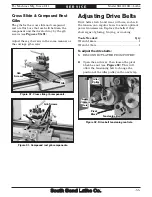
Page 57: ...components Gib Gib Screws Adjusting Drive Belts Drive belts stretch and wear with use so check the tension on a regular basis to ensure optimal power transmission Replace the belts if they show signs...

Page 58: ...ied to the belt between the pulleys see Figure 93 Figure 93 Testing for correct drive belt tension Pulley Deflection Pulley 4 When the belt tension is correct continue applying pressure on the idler p...

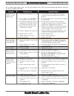
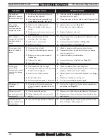
Page 59: ...g 1 Re tension drive belts see Page 55 re position timing belt pulleys so that the timing belts have only slight deflection between pulleys 2 Timing belt pulleys are loose or missing shaft keys 2 Re t...

Page 60: ...ool sticks too far out of tool holder lack of support 2 Re install cutting tool so no more than 1 3 of the total length is sticking out of tool holder 3 Gibs are out of adjustment 3 Adjust gib screws...

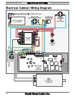
Page 61: ...ing serious injury or fire Motor Wiring The motor wiring shown in these diagrams is current at the time of printing but it may not match your machine Always use the wiring diagram inside the motor jun...

Page 62: ...n YK 92 BL 001 1100W 14A Fan Heat Sink Ancer Model 750 Type M 115VAC 110V Power Receptacle EMI Filter Canny Well CW2B 10A T 002 Tachometer Display Ancer RPM320 Contactor ABB A12 30 10 Spindle Switch A...

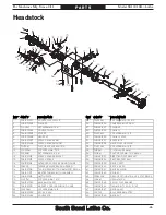
Page 63: ...BRACKET 37 PSB1001037 DIRECTION PIVOT BRACKET 13 PSB1001013 SPEED SENSOR 38 PSB1001038 PIVOT BRACKET BOLT 14 PSB1001014 OUTBOARD SPINDLE BEARING FLANGE 39 PSB1001039 GEAR SHAFT 15 P32009 TAPERED ROLL...

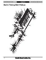
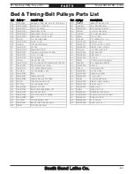
Page 64: ...5 105 105 106 106 107 107 107 108 109 110 111 112 113 114 115 116 116 117 118 119 120 121 122 123 123 124 124 125 125 126 127 128 128 129 130 131 132 133 134 135 136 136 136 137 138 139 140 141 142 14...

Page 65: ...K 114 PSB1001114 PIVOT BRACKET 146 PSB1001146 SPACER 115 PN03M HEX NUT M8 1 25 147 PR29M INT RETAINING RING 32MM 116 PSB1001016 TAP IN GREASE FITTING 6MM STRT BRASS 148 P6002ZZ BALL BEARING 6002ZZ 117...

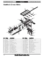
Page 66: ...B1001223 GRADUATED DIAL 208 PSB1001208 GIB CLAMP PLATE 224 PCAP33M CAP SCREW M5 8 X 12 209 PCAP02M CAP SCREW M6 1 X 20 225 P6800ZZ BALL BEARING 6800ZZ 210 PSS53M SET SCREW M5 8 X 12 226 PSB1001226 BEA...

Page 67: ...PRESSION SPRING 326 PSTB004M STEEL BALL 5MM 309 PSB1001309 COMPOUND REST 327 PSB1001327 COMPOUND REST GIB 310 PSS57M SET SCREW M5 8 X 20 328 PN46M HEX NUT M8 1 25 THIN 311 PN06M HEX NUT M5 8 329 PCAP1...

Page 68: ...410 PINION SHAFT END CAP BRASS 432 PSB1001432 DOWEL PIN 5 X 16 411 PSB1001411 GEAR SHAFT BRACKET 433 PK69M KEY 4 X 4 X 12 412 PSB1001412 APRON 434 PSB1001434 HALF NUT BRACKET 413 PSB1001413 PINION SHA...

Page 69: ...SCR M3 5 X 6 508 PSB1001508 TAILSTOCK CASTING 524 PSB1001524 OFFSET INDICATOR 509 PSB1001509 SET SCREW M6 1 X 10 PILOT 525 PB82M HEX BOLT M8 1 25 X 80 510 PSB1001016 TAP IN GREASE FITTING 6MM STRT BRA...

Page 70: ...OMPRESSION SPRING 608 PSB1001608 EMERGENCY STOP BUTTON ASSY 625 PN46M HEX NUT M8 1 25 THIN 610 PSB1001610 CONTACTOR ABB A12 30 10 110V 626 PW01M FLAT WASHER 8MM 611 PCAP50M CAP SCREW M5 8 X 10 627 PSB...

Page 71: ...PSB1001708 TIMING BELT PULLEY XL 20T 725 PSB1001725 DEAD CENTER MT 2 709 PSB1001709 TIMING BELT PULLEY XL 19T 726 PSB1001726 TAPERED SPINDLE SLEEVE MT 4 5 MT 3 710 PSB1001710 TIMING BELT PULLEY XL 18...

Page 72: ...ON 801 PSB1001801 MACHINE ID LABEL 810 PSBLABEL13VS DOOR CLOSED LABEL 802 PSB1001802 EMERGENCY STOP LABEL 811 PSB1001811 SB NAMEPLATE CURVED BRASS 803 PSB1001803 SPINDLE SPEED DIAL LABEL 812 PSB100181...

Page 73: ......

Page 74: ......

Page 75: ...ies with the provisions of any law act code regulation or standard of any domestic or foreign government industry or authority In no event shall South Bend s liability under this warranty exceed the o...

Page 76: ...Printed In China TS14279...

Reviews: