(Continued from page 9)
LEVEL SETTING
The subwoofer channel has separate On/Off controls on both the front and rear
inputs for constant for
bass. When the switch labeled “SUB CONTROL”
for either the front or rear channels is in the “ON” position, low frequencies from
those channels are directed to the subwoofer output. In the “OFF position, low
frequencies from those channels are ignored.
SUBSONIC FILTER
The subwoofer channel also has the option of an
per octave filter to
suppress harmful subsonic signals. When the switch labeled “SUB-SONIC” is in
the “IN” position, there is an
per octave high pass filter placed on the
subwoofer outputs, variable from 20 to 50 Hz (or 27 to 70 Hz, depending on the
filter setting).
APPLICATION
Woofers in vented enclosures have good power handling characteristics above
the tuning frequency, but below the tuning frequency, power handling drops off
considerably. This is due to the loss of any appreciable resistive air mass. At
frequencies below resonance, the woofer starts to behave as if it were mounted in
“free-air”. If we wish to improve the performance of a vented system, we should
remove these unwanted signals. They can be removed by adding the subsonic
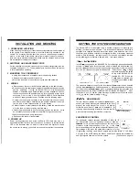
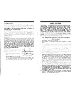
filter. Figure shows the effectiveness of a subsonic filter on woofer excursion.
Woofer travel is 7.5 mm at 10 Hz, with the subsonic filter properly adjusted, this
excursion can be reduced to less than 1 mm. This is of great benefit to lowering
woofer distortion and increasing output.
1
ADJUSTMENT
An easy method of optimizing your existing
subwoofer enclosure with the X.0 subsonic
filter control is as follows:
-1
1 .
Adjust frequency control to full CCW po-
- 3
2.
While listening to music with strong bass
FIG
1
Limited Excursion
content at a moderate level, slowly adjust frequency control clockwise. Listen
for a reduction of bass response. Now, rotate frequency control slightly back-
wards. This serves the purpose of removing the “subsonic” bass energy.
The BALANCED X.0 has variable input levels which are adjusted by means of the
individual channel level controls located on the front of the crossover. However,
all of the input and outputs gain controls of the BALANCED X.0 are bypassed
when the switches on top of the crossover labeled “Input Level” are set to “IN”.
Either way, the BALANCED X.0 will have enough flexibility to get a good audio
balance in any car stereo system. By setting all components to reach clipping at
the same time, you can maximize the output of your system. For the
amplifiers, follow the steps below for the quickest, easiest means of setting the
levels. For systems which incorporate the BLT
BALANCED X.0 and
amplifiers equipped with the balanced signal input, please follow these
steps for the quickest, easiest means of setting the levels.
1.
2.
3.
4.
5.
6.
7.
8.
9.
Level Setting the BALANCED X.0 with the Direct 5V Input
(Recommended)
Disconnect any speakers from the amplifiers.
Switch the inputs of the amplifiers receiving the balanced input to the “BAL
position.
Turn the amplifiers’ input level controls to the minimum (5 volts) position (fully
counter-clockwise), and switch the amplifiers’ input level selector to the 0.5 5.0
Volt position.
Turn the
input level controls to the minimum position (fully counter-clock-
wise).
Set the switches on top of the BALANCED X.0 labeled “INPUT LEVEL” to the
position. Set all frequency controls on the BALANCED X.0 to their respec-
tive 12 o’clock positions.
Turn the system on, and verify all of the components are “ON”. Set source unit
volume to approximately
of full volume.
While playing extremely dynamic source material or a test tone, slowly increase
the
input level until the red LED labeled “REFERENCE” on the top of the
BLT begins to blink. This calibrates the input sensitivity of the BLT to the level of
your head unit. (NOTE: To set the BLT level, Soundstream recommends using
the Autosound 2000 Compact Disc
Track 27, 1
0
“all bits high”
tone. If this CD is not available, a similar tone from a test CD can be used, or an
extremely dynamic CD with a high crest factor. Remember; the “loudest” CD
you have may not be the most “dynamic”!)
Next, with the source material still playing, adjust the input levels of your ampli-
fiers so that the amplifiers input LED’s begin to blink as well. Since in step 7
you’ve set up the BLT to transmit a 5 volt signal, and in step 3 you set the
amplifier up to clip upon receiving a 5 volt input signal, the BLT4 LED and the
output clipping LED’s on the amplifier should blink at about the same level.
Turn the system down, and reconnect the speakers. If the volume out of your
amplifier is not loud enough, turn up the gain adjustments on the front of the
amplifier receiving the BLT input.
IO. If the amplifier volume is too loud, and the amplifier gain controls are already
turned to the minimum position, turn down the level of the transmitted signal by
adjusting the level controls on the top of the BLT.
10
11
Summary of Contents for Balanced X.0
Page 9: ...____ I I...


