1 .
2.
3.
4.
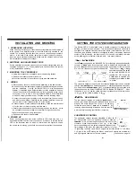
INSTALLATION AND MOUNTING
CROSSOVER LOCATION
When mounting the crossover, it should be securely mounted to either a
panel
in
the vehicle or an amplifier board or rack that is securely mounted to the
vehicle. The mounting location should be either in the passenger compart-
ment or in the trunk of the vehicle, away from moisture, stray or moving ob-
jects, and major electrical components. Make sure the switches and trim pots
are accessible for setting the crossover.
SWITCHES AND ADJUSTMENT POTS
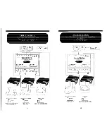
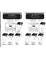
Set the switches on top of the crossover for your system configuration (see the
examples on pages 14 17). The adjustment pots can be set when the system
is fully installed and operating.
MOUNTING THE CROSSOVER
a. Using the crossover as a template, mark the mounting surface.
b. Remove the crossover and drill the holes.
c. Mount the crossover to the surface using the provided hardware.
WIRING
a. Disconnect any fuses or circuit breakers pertaining to the audio system.
b. Run and connect the audio signal cables to the balanced line audio source
and the amplifiers.
If using the BALANCED X.0 with Soundstream
amplifiers with a balanced input (or other amplifiers which use
the same connector with phantom power), this is the only wiring that is
necessary. Go on to step 5. If using the BALANCED X.0 with amplifiers
which don’t supply phantom power, continue with the following steps:
Connect the remote turn-on cables to the crossover from the source unit
and also to the amplifiers. Carefully run the positive cable from the ampli-
fier to a fuse or circuit breaker within 18” of the battery.
Connect the fuse or circuit breaker to the battery. Leave the circuit breaker
off or the fuse out until everything is bolted down.
C
d
e. Secure the ground cable to a solid chassis ground on the vehicle. It may
be necessary to sand paint down to raw metal for a good connection.
f. Double check each and every connection!
g. Re-connect the fuse or circuit breaker.
5. POWER UP
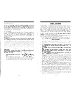
Power up the system and look at the red Power LED; there may be a 2 -3
second delay from the time
the the source unit is turned on to the time that the
LED on the crossover turns on, which is normal. Once the system is on and
the source unit is playing, you should have sound coming from the speakers.
SETTING THE SYSTEM CONFIGURATION
The BALANCED X.0 is designed to be a flexible component for planning and
building your ideal car audio system. This three-channel electronic crossover is
equipped with separate front and rear stereo inputs (each balanced pair in one
connector), and includes controls for configuring two-way or three-way crossover
systems. With this design, the fader control (on the head unit) always remains
active, allowing you to achieve a desired front rear sound balance.
MODE
In the
configuration, the BALANCED X.0 provides high pass and subwoofer
outputs. In
mode, incoming stereo audio is divided into band-limited out-
puts for
operation on the front speaker, high pass output for the rear speak-
ers, and low frequency outputs for subwoofers.
Select either
or
operation by setting the switch
on top of the BALANCED X.0
labeled “2W 3W”. When the
mode is selected, use
the
crossover marking written
in “yellow”.
Low
High-Pass
Low
High-Pass
Pass
Pass
Front Channel (2
Front Channel
The crossover frequency range for the front channel
output can be selected
to drive either
and satellite speakers, or midrange speakers and tweet-
ers. Select either
(xl)
or midrange/tweeter (x4) operation with
the pushbutton
on
the front of the BALANCED X.0 labeled “FREQ MULT”.
When
the button is “out” (xl), use the yellow markings in standard text. When the button
is “in”
use the yellow markings in
DE-EMPHASIS
The rear channel features an innovative
de-em-
phasis circuit which places more emphasis on the front
stage of the audio system. The circuit is a 6
per
octave low pass filter at 7
and is defeatable.
By
removing upper frequency information from the rear fill,
a more natural sounding rear fill effect is created.
SUBWOOFER CONTROL
The subwoofer channel contains selectable 12
or 24
per octave filters to set the “tightness” contour of bass fre-
This is set with the pushbutton on the front of the
crossover. When the pushbutton is “out” (i.e., in the 12
per octave setting) use the yellow subwoofer frequency con-
trol markings. Also, when the subwoofer crossover is in the
12
setting, the Mono 1 and Mono 2 outputs are in stereo (Mono 1 = Left, Mono
2 = Right). In the 24
setting, the Mono 1 and Mono 2 outputs are summed left
and right signals, identical on the two outputs.
(Continued on page
IO)
Summary of Contents for Balanced X.0
Page 9: ...____ I I...


