


- 10 -
A10-TX User Guide
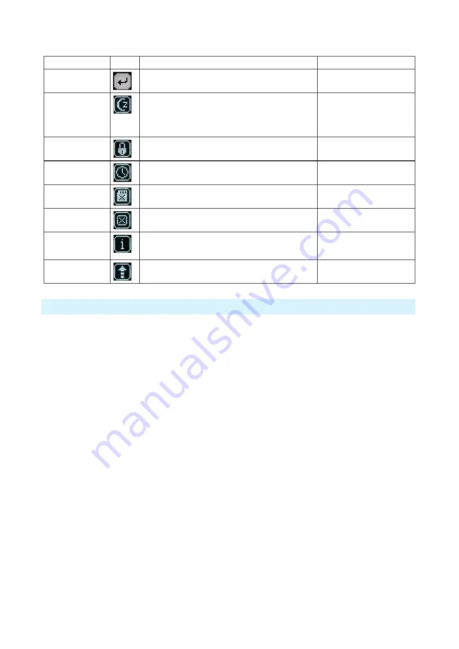
System Menu
Selections
Icon
Description
Options
Exit
Returns to the main menu.
Sleep
When selected, the A10-TX goes into low-power Sleep
mode. The blue LED flashes when the unit is in a sleep state.
The unit returns to normal power operation when any button
is pressed or the transmitter is activated from the A10-TX
Remote App.
• Sleep
Lock Menu
Activates a button lock to prevent unintentional changes to
menu selections.
• Unlock
• Lock
Set Time / Date
Sets the time and date of the realtime clock. This value is
applied to any recorded files.
Format Card
Deletes all files and data present on the inserted microSD
card and prepares it for new recordings.
OK - begins formatting process.
Restore
The restore function allows the user to reset the A10-TX to
the factory default settings.
Info
Shows numerous attributes of the transmitter.
• Serial Number
• Firmware Revision
• Frequency Band
Update (Firmware)
Updates the firmware of the transmitter using a firmware
.PRG file on the microSD card.
Basic Operation
Frequency Selection
The A10 Digital Wireless System operates in the UHF frequency band from 470 to 694 MHz.
There are three models (two in some geographic markets) of the A10-TX transmitter to cover
this frequency range.
Multiple A10 Digital Wireless systems can be used simultaneously on nearby adjacent
frequencies without worry of intermodulation interference since the A10 Digital Wireless System
and its digital RF transmission is inherently immune to intermodulation. Systems can be used
together when separated by at least 400 kHz. Use the scan tool on the A10-RX receiver to search
for available frequencies.
ª
When using A10 Digital Wireless systems in conjunction with analogue RF systems, an
intermodulation plan needs to be addressed for analogue receivers.
Channel, Sub Channel, Tune
To simplify frequency selection, frequencies are divided into channels and sub channels.
Frequencies corresponding to channels and sub channels depend on the TV Channel Mapping
selected in the Systems menu. Three options are available, 6, 7, and 8 MHz spacing, X, Y, and Z
respectively. These three settings generally correspond to three main geographic regions, USA,
Australia/New Zealand, and Europe, respectively.
• Channel
- corresponds to broadcast television channels used in geographic regions.
Depending on the selected channel mapping, channels cover 6, 7, or 8 MHz.
• Sub Channel
- channels are divided in 400 kHz increments called sub channels to speed up
frequency selection. The number of sub channels depends on the channel mapping selected.


