28 von 36
service record Airon
2021-06-10
3.9
Pads assembly
3.9.1 Nomenclature
(1)
The pads are made up of the following
parts:
• (1A)
Locking hinge
• (1B)
Connection (C-rail)
• (1C)
Lateral support pads
• (1D)
Pad holder
• (1E)
Release button
(B)
(1)
(C)
(D)
(A)
(E)
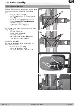
3.9.2 Vertical adjustment
(2)
The vertical adjustment of the pads is done
on the one hand by moving the locking joint
(2A)
in the C-rail
(2B)
:
• Loosen both screws
(2C)
,
• move the locking joint
(2A),
• and tighten the screws
(2C)
again.
(3)
The locking joint
(3A)
is clamped into the
C-rail
(3D)
by connecting the metal tongue
(3B)
with the two screws
(3C)
.
(3)
On the other hand, the pads can be adjus-
ted by moving the C-rail
(3D)
on the back tube
holder:
• If necessary, loosen the two screws
(3B)
and thread the pad holder
(3A)
out of the
C-rail
(3D)
.
• Remove the screws
(3E)
• and move the C-rail
(3D)
along the alter-
native holes
(3F)
,
• insert the screws
(3E)
again
• and screw it back tight.
• Then thread the pad holder
(3A)
into the
C-rail
(3D)
,
• adjust it to the desired height
• and tighten the screws
(3B)
again.
(4)
In addition, the height of the size II pads can
be changed by moving the pads:
• Remove the cover,
• remove both screws
(4A)
,
• move the pad
(4B)
into the alternative
holes
(4C)
,
• reinsert both screws
(4A)
and tighten
them tightly.
• Then put the covers back on.
(2)
(3)
(A)
(B)
(C)
(4)
(B)
(C)
(A)
(A)
(E)
(F)
(B)
(C)
(D)


