background image

Chapt

er

 4   
P

la

y

bac

k

36

4-3 Thumbnail Search

4-3 Thumbnail Search

4-3-1 Cuing Up a Desired Clip

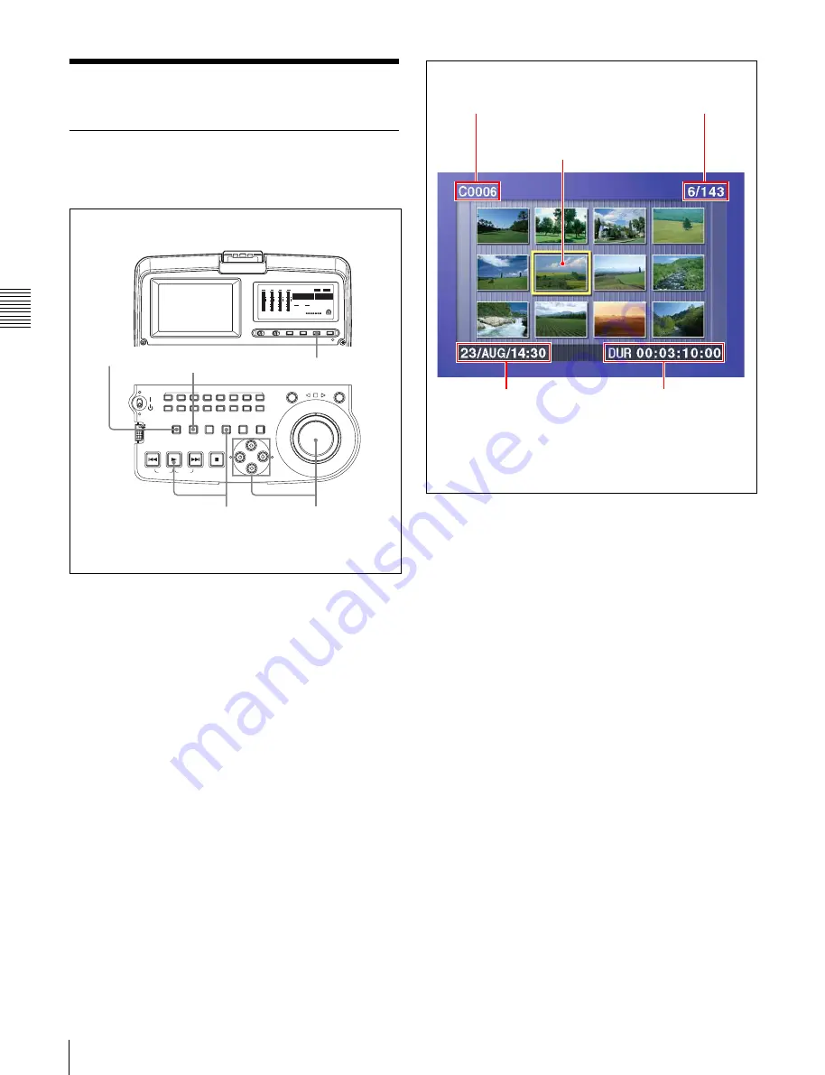
To display the thumbnail images of all clips on the disc, 
and cue up a desired clip, proceed as follows.

1

With the SUBCLIP button off, press the 
THUMBNAIL button, turning it on.

The thumbnails of clips on the disc appear.

To switch between duration and time code display 
in the thumbnail display

Press the COUNTER button. Each press of the button 
toggles between duration display and time code 
display.

To escape from the thumbnail display to the full-
screen display

Press the THUMBNAIL button, turning it off.

2

Use the arrow buttons or the jog dial to select the 
desired clip.

You can select clips with the following operations.

Press the PREV or NEXT button:

 Move to the 

previous or next clip.

Press the PREV or NEXT button with the SHIFT 

button held down:

 Move to the first or last clip.

Press the 

f

 or 

F

 button with the SHIFT button held 

down:

 Switch to the  previous or next page.

3

To cue up the selected clip, press the SET button.
To start playback from the selected clip, press the 
PLAY button.

ACCESS

L

R

NETWORK
LOCAL
REMOTE

AUDIO MONITOR

L

R

CH-1

CH-2

CH-3

CH-4

CH-5

CH-6

CH-7

CH-8

SHUTTLE

JOG

THUMBNAIL

ESSENCE

MARK

MARK1

MARK2

IN

OUT

MENU

S.SEL

SET

RESET

SHIFT

TOP

F REV

F FWD

END

PREV

NEXT

PLAY

STOP

CLIP

MENU

SYSTEM

MENU

-30

dB

-12

-20

-40

-60

0

CH- 15

DATA

OVER

-30

dB

-12

-20

-40

-60

0

CH- 26

DATA

OVER

-30

dB

-12

-20

-40

-60

0

CH- 37

DATA

OVER

-30

dB

-12

-20

-40

-60

0

CH- 48

BATT

E

F

DATA

OVER

VITC

HOURS

AUDIO

625

IMX 50 40 30

[

]

525

4 8 CH

16 24 BIT

DVCAM

MINUTES

SECONDS

FRAMES

COUNTER

VIUB

VITC

ALARM

SUBCLIP

3

2

1

COUNTER button

SUBCLIP button

Name of currently 
selected clip

 a)

Thumbnail of currently selected clip 
(first frame or specified

 b)

 frame)

Sixth clip is selected 
from a total of 143 clips.

Duration of selected clip 
or time code of first frame

Recording date and 
time of selected clip

a) When a title has been assigned to a clip, the title is enclosed in double 

quotation marks, for example “TITLE00001.”

b) The thumbnail frame can be specified by setting of a disc recorder.

Summary of Contents for XDCAM PDW-V1

Page 1: ...PROFESSIONAL DISC RECORDER PDW V1 OPERATION MANUAL English 1st Edition Revised 4 ...

Page 2: ...expose this apparatus to rain or moisture To avoid electrical shock do not open the cabinet Refer servicing to qualified personnel only THIS APPARATUS MUST BE EARTHED CAUTION The apparatus shall not be exposed to dripping or splashing and no objects filled with liquid such as vases shall be placed on the apparatus The unit is not disconnected from the AC power source mains as long as it is connect...

Page 3: ...Å ANNAT SÄTT ÄN I DENNA BRUKSANVISNING SPECIFICERATS KAN ANVÄNDAREN UTSÄTTAS FÖR OSYNLIG LASERSTRÅLNING SOM ÖVERSKRIDER GRÄNSEN FÖR LASERKLASS 1 For the customers in the USA This equipment has been tested and found to comply with the limits for a Class B digital device pursuant to Part 15 of the FCC Rules These limits are designed to provide reasonable protection against harmful interference in a ...

Page 4: ...rmity to the following European standards EN60065 Product Safety EN55103 1 Electromagnetic Interference Emission EN55103 2 Electromagnetic Susceptibility Immunity This product is intended for use in the following Electromagnetic Environment s E1 residential E2 commercial and light industrial E3 urban outdoors and E4 controlled EMC environment ex TV studio Voor de Klanten in Nederland Gooi de batte...

Page 5: ...a Frame Including an Essence Mark 37 4 4 Clip List Playback 38 4 4 1 Playing Back in Clip List Order 38 4 4 2 Cuing Up With Sub Clip Thumbnails38 4 5 Repeat Playback 39 4 6 Locking and Deleting Clips 39 4 6 1 Locking Clips 39 4 6 2 Deleting Clips 40 Chapter 5 Scene Selection 5 1 Overview 42 5 2 Creating Clip Lists 45 5 2 1 Selecting Clips 45 5 2 2 Reordering Sub Clips 47 5 2 3 Trimming Sub Clips 4...

Page 6: ...ions 82 7 3 3 Using UMID Data 84 7 4 Maintenance Menu 86 7 4 1 Items in the Maintenance Menu 86 7 4 2 Maintenance Menu Operations 88 7 5 System Menu 91 7 5 1 Items in the System Menu 91 7 5 2 System Menu Operations 91 Chapter 8 Maintenance and Troubleshooting 8 1 Periodic Maintenance 93 8 1 1 Digital Hours Meter 93 8 2 Error Messages 94 8 3 Alarms 94 8 3 1 Alarm List 94 8 4 Condensation 100 Append...

Page 7: ... 625 SYSTEM SELECT See 7 2 2 Basic Menu Operations page 74 for more information about how to make basic menu settings Note The line mode is not set or is cleared in the following situations Reset the line mode The unit is powered off before performing step 4 in the previous procedure The RESET ALL SETUP command in the maintenance menu see page 86 is executed Settings affected by the line mode The ...

Page 8: ...9H to 19H to 22H 602 VITC POSITION SEL 2 12H to 18H to 20H 9H to 21H to 22H 628 DF MODE Item No item 652 UMID SDI VANC LINE 12 H to 17 H to 19 H 9 H to 17 H to 18 H 660 ESSENCE MARK SDI VANC LINE 12 H to 17 H to 19 H 9 H to 17 H to 18 H 703 BLANK LINE SELECT Setting range ALL LINE LINE 12 to LINE 20 525 U LINE 12 to LINE 21 525 J Setting range ALL LINE LINE 9 322 to LINE 22 335 LINE 23 713 VIDEO S...

Page 9: ...eeds The proxy AV data can be transferred at upto 30 times faster than real time Thumbnail search operation Simply press the THUMBNAIL button and the PDW V1 instantly displays these thumbnails on either its LCD display or a connected monitor You can easily cue up the desired scene by guiding the cursor to the corresponding thumbnail and confirming your selection with the SET button Scene selection...

Page 10: ...e material This metadata can be used in applications such as the following The supplied PDZ 1 Proxy Browsing Software can be used to add titles comments and other text data to discs and clips Computer readable text files can be recorded on the Professional Disc to allow systematic content management The ability to search metadata for the required audio and video scenes brings greater efficiency to...

Page 11: ...ce with the MPEG 4 Visual Standard MPEG 4 Video and or ii decoding MPEG 4 Video that was encoded by a consumer engaged in a personal and non commercial activity and or was obtained from a video provider licensed by MPEG LA to provide MPEG 4 Video No license is granted or shall be implied for any other use Additional information including that relating to promotional internal and commercial uses an...

Page 12: ...ied see page 102 AC power switch rear panel Press to power on press a to power off Battery pack shoe covered see page 26 Connectors see page 20 Disc slot and EJECT button see page 30 Control panel see page 13 LCD panel see page 17 Shoulder belt posts see page 103 Security slot You can fit a commercially available security cable into this slot a a For information about how to use your security cabl...

Page 13: ... standby 1 states When the switch is moved to the position the indicator lights When the switch is moved to the 1 position the indicator goes off When operating the PDW V1 from an AC power supply normally leave the AC power switch in the position and switch the PDW V1 between the operating and standby states using the on standby switch d AUDIO MONITOR audio monitor channel selection buttons Each o...

Page 14: ...sition If the shuttle dial is not in the center position it is possible occasionally for vibration from other operations to activate the dial and start playback in shuttle mode e Jog dial Turn this for playback in jog mode Turn clockwise for forward direction playback and counterclockwise for reverse direction playback In jog mode the playback speed varies in the range 1 times normal speed accordi...

Page 15: ...ssence mark frames appear in thumbnails Press once more turning the button off to return to a whole screen display c MENU button Use for setup menu operations Pressing this displays the setting of a setup menu item in the time data display see page 74 Press once more to return to the original display The system menu see page 91 appears in the status display section and on an external monitor when ...

Page 16: ...h in the forward direction is carried out Displaying the last frame of the last clip Hold down the SHIFT button and press this button d STOP button To stop playback press this button turning it on The frame at the stop point appears The unit enters standby off mode when you press this button with the SHIFT button held down It returns from standby off mode to the original state when you press this ...

Page 17: ...show the audio levels for channels 1 to 4 or channels 5 to 8 When the audio level exceeds 0 dB on any channel the indicator for that channel lights 30 dB 12 20 40 60 0 CH 15 DATA OVER 30 dB 12 20 40 60 0 CH 26 DATA OVER 30 dB 12 20 40 60 0 CH 37 DATA OVER 30 dB 12 20 40 60 0 CH 48 BATT E F DATA OVER VITC HOURS AUDIO 625 IMX 50 40 30 525 48CH 16 24 BIT DVCAM MINUTES SECONDS FRAMES COUNTER VIUB VITC...

Page 18: ...the number of channels recorded on the disc and the number of quantizing bits Number of channels 4ch 4 channels 8ch 8 channels Number of quantizing bits 16bit 16 bits 24bit 24 bits d BATT battery display This shows the battery charging state as follows xxxxxxx 7 segments lit Adequately charged As the battery discharges the number of LED segments lit decreases BATT flashing Almost exhausted Operati...

Page 19: ... sequence TC Playback time code read by the internal time code reader The selection of TC or VITC is made by the TC VITC button UB User bits included in the playback time code COUNTER The elapsed playback time hours minutes seconds frames This can be reset by pressing the RESET button see page 15 The corresponding indicator in the time data display lights to reflect the setting The factory default...

Page 20: ... devices Notes If video or audio signals from an external device connected with the S400 i LINK connector are not output disconnect the i LINK cable and connect it again pushing it straight in When the PDW V1 is connected to a device with a 6 pin i LINK connector by an i LINK cable before unplugging the i LINK cable first power off the device and disconnect the power plug from the outlet If the i ...

Page 21: ...HARACTER button see page 19 f AUDIO MONITOR OUT L R connectors pin jacks Output the audio signals for the channels selected with the AUDIO MONITOR button L and R rows on the control panel Non audio signals are muted g SDI serial digital interface OUT connector BNC type Outputs an SDI video audio signal The time code menu settings alarm messages or other text information can be superimposed on the ...

Page 22: ...bles you to see the output video on the monitor screen Example connections are shown in the following When connecting to the MONITOR connector Note Set the PC compatible display or data projector to which to connect this unit for VGA input beforehand VIDEO OUT MONITOR SDI OUT AUDIO MONITOR OUT L R S400 MONITOR PDW V1 1 1 D sub 15 pin cable not supplied RGB input connector PC compatible display Dat...

Page 23: ...ansfer Protocol connection Note To use PDZ 1 requires the PDW V1 IP address and other network related settings to be made beforehand For details of the network related settings see To change network settings page 89 VIDEO OUT MONITOR SDI OUT AUDIO MONITOR OUT L R S400 2 1 VIDEO OUT SDI OUT PDW V1 Video monitor To composite video input connector 1 2 75 Ω coaxial cable not supplied To SDI input conn...

Page 24: ...Z 1 software Some limitations apply to FAM connections For details see 6 2 File Access Mode File Operations page 60 VIDEO OUT MONITOR SDI OUT AUDIO MONITOR OUT L R S400 1 1 1 PDW V1 VIDEO OUT MONITOR SDI OUT AUDIO MONITOR OUT L R S400 PDW V1 VIDEO OUT MONITOR SDI OUT AUDIO MONITOR OUT L R S400 PDW V1 1 1 Network cable not supplied a Laptop computer network connector To network connector Connecting...

Page 25: ...DE to select either of the following 4ch 12 bit 32 kHz 4 ch 2ch 16 bit 48 kHz 2 ch Factory default setting Audio output channel selection Select the audio output channels with extended menu item 828 SDI DV AUDIO OUTPUT SELECT For information about how to make extended menu item settings see 7 3 2 Extended Menu Operations on page 82 For the method of transferring video audio signals AV C data to a ...

Page 26: ...s of these menus are as follows Basic setup menu Items relating to the hours meter Items relating to operation Items relating to menu banks Extended setup menu Items relating to control panels Items relating to the remote control interface Items relating to editing operations Items relating to preroll Items relating to disc protection Items relating to the time code reader metadata and UMID Items ...

Page 27: ...setting of the flashing digits To change the flashing digits Use the arrow buttons G g To increase or decrease the values of the flashing digits Use the arrow buttons F f or jog dial 4 Press the SET button The date time and time zone settings are stored To return to the previous menu page Press the MENU button To exit the menu Press the MENU button twice in succession Note The time zone is reset t...

Page 28: ...time data OUT OUT point time data DUR Duration between IN point and OUT point T C R 0 0 0 4 4 7 0 7 B 1 P L A Y L O C K 5Operation mode 1Type of time data 2Time code reader drop frame mark for 525 line mode only 3VITC field mark Time data 6 Playback condition mark 4Menu setting states Display Description B1 The current menu settings are the same as the settings in menu bank 1 B2 The current menu s...

Page 29: ...ck the total optical output time of optical heads For details see 8 1 1 Digital Hours Meter page 93 about this setting Refer to the Maintenance Manual for an approximate guide to when it is time to replace optical heads To prevent playback conditions from deteriorating Pay attention to the following points when handling discs Do not open disc cartridges and touch discs directly with your hands Do ...

Page 30: ...here the temperature or humidity is high Do not leave cartridges where dust may be able to gain ingress Store cartridges in their cases Care of the discs Remove dust and dirt on the outside of a cartridge using a soft dry cloth If condensation forms allow ample time to dry before use 3 6 3 Write Protecting Discs To protect the content recorded on the disc from accidental erasure move the Write Inh...

Page 31: ...scs in succession 1 1 Carry out steps 1 to 5 in the previous procedure and then press the EJECT button to eject the disc 2 Insert the next disc that you want to format The message QUICK FORMAT OK appears 3 Press the SET button 4 When the message FORMAT COMPLETED appears press the EJECT button to eject the disc 5 Repeat steps 2 to 4 for all of the discs that you want to format 1 This is supported f...

Page 32: ...off is loaded into this unit clips are reconstructed on the basis of markers recorded on the disc Processing time is about 30 seconds although it depends on the state of the disc Proceed as follows to perform a full salvage 1 Insert the disc on which recording did not end normally The message Salvage appears 2 Do one of the following To salvage Press the SET button Processing begins and the messag...

Page 33: ... power on When using a battery pack fit the battery pack to the battery pack shoe beforehand See page 26 TC VITC button Select TC or VITC to display the time code recorded on the disk in the time data display See page 19 COUNTER button Select the data to be displayed in the time data display See page 19 AUDIO MONITOR buttons Select the audio channel to monitor See page 13 On standby switch Set the...

Page 34: ... For details of how to insert a disc see 3 6 4 Loading and Unloading a Disc on page 30 To start playback Press the PLAY button Playback starts When two or more clips are recorded on the disc they are played back continuously Note No audio is output when non audio signals are played back To jump to the next or previous clip then start playback Use the PREV button NEXT button jog dial or shuttle dia...

Page 35: ...to the desired angle corresponding to the desired playback speed Playback in shuttle mode starts 3 To stop playback in shuttle mode return the shuttle dial to the center position or press the STOP button When extended menu item 101 SELECTION FOR SEARCH DIAL ENABLE is set to dial factory default setting just turning the shuttle dial with the SHUTTLE button off starts playback in shuttle mode To alt...

Page 36: ...down Switch to the previous or next page 3 To cue up the selected clip press the SET button To start playback from the selected clip press the PLAY button ACCESS L R NETWORK LOCAL REMOTE AUDIO MONITOR L R CH 1 CH 2 CH 3 CH 4 CH 5 CH 6 CH 7 CH 8 SHUTTLE JOG THUMBNAIL ESSENCE MARK MARK1 MARK2 IN OUT MENU S SEL SET RESET SHIFT TOP F REV F FWD END PREV NEXT PLAY STOP CLIP MENU SYSTEM MENU 30 dB 12 20 ...

Page 37: ...esired frame You can select frames with the following operations Press the PREV or NEXT button Move to the previous or next frame Press the PREV or NEXT button with the SHIFT button held down Move to the first or last frame Press the F or f button with the SHIFT button held down Switch to the previous or next page 5 Press the SET button to cue up the selected clip To start playback from the select...

Page 38: ...ppear To switch between duration and time code display in the thumbnail display Press the COUNTER button Each press of the button toggles between duration display and time code display To escape from the thumbnail display to the full screen display Press the THUMBNAIL button turning it off 2 Use the arrow buttons or the jog dial to select the sub clip you want to cue up You can select sub clips wi...

Page 39: ... except the PLAY button or operate the jog or shuttle dial The unit executes the operation for the button press or jog or shuttle dial operation The unit enters search mode when you conduct a search and stop mode at the end of the disc To disable repeat playback Set extended menu item 142 REPEAT MODE to off 4 6Locking and Deleting Clips In the thumbnail screen you can delete selected clips or lock...

Page 40: ...n press the SET button A confirmation screen appears To cancel the lock operation and return to the thumbnail screen Do one of the following Use the G or g button to select CANCEL and then press the SET button Press the RESET button 3 Use the G or g button to select OK and then press the SET button All clips are locked and you return to the thumbnail screen To unlock all clips Carry out the proced...

Page 41: ...es the clip will also be deleted To go to the clip deletion screen without displaying the THUMBNAIL MENU After step 2 press the RESET button with the SHIFT button held down shortcut operation To cancel the deletion and return to the thumbnail screen Do one of the following Use the F or f button to select CANCEL and then press the SET button Press the RESET button 5 Use the F or f button to select ...

Page 42: ...ips from the material recorded on a disc and perform cut editing You can do this by operating on this unit only Scene selection is a convenient way to perform cut editing in the field and in other offline situations Clip lists edit data created with the scene selection function can be used on XPRI and other full feature nonlinear editing systems ...

Page 43: ... Reordering sub clips see page 47 Trimming sub clips see page 49 Deleting sub clips see page 50 Previewing clip lists see page 50 Save the clip list to disc see page 50 Play back the clip list see page 38 Disc PDW V1 PDW 510 530 510P 530P Clip 1 Clip 2 Clip 3 SubClip1 Sub Clip 2 SubClip3 Clip 1 Clip 2 Clip 3 Clip list 1 Disc SubClip1 Sub Clip 2 Sub Clip 3 PDW V1 Recorded material Clip list 1 Selec...

Page 44: ...re virtual data specifying ranges in the original clips Clip data in the original clips is not overwritten Clip list editing current clip list Clip lists cannot be edited on disc To edit clip lists you need to load them one at a time into the unit memory The clip list which is currently loaded into the unit memory is called the current clip list The current clip list is always the target of sub cl...

Page 45: ...elect from the thumbnail screen 1 With the SUBCLIP button off press the THUMBNAIL button turning it on Thumbnails of the clips on the disc appear Unit memory Current clip list Can be edited adding deleting and reordering sub clips SAVE m t Clip list playback and thumbnail display C0001 Clip 1 C0002 Clip 2 C0003 Clip 3 E0001 Clip list 1 E0002 Clip list 2 E0003 Clip list 3 E0099 Clip list 99 M LOAD ...

Page 46: ...the same clip any number of times The scene selection window displays thumbnails of the sub clips that have been added to the current clip list The cursor in the window indicates the position where the next sub clip will be added To move the cursor in the scene selection window After carrying out step 3 to display the scene selection window press the G or g button 6 When you have finished selectin...

Page 47: ...ent clip list as a sub clip When you set In and Out points stretching across several clips One sub clip is created for each of the clips 5 Repeat steps 1 to 4 until you have added all of the clips you want to the current clip list 6 Save the current clip list to disc See 5 2 6 Saving the Current Clip List to Disc page 50 5 2 2 Reordering Sub Clips 1 Press the SUBCLIP button turning it on 2 Press t...

Page 48: ... operation menu appears To return to the thumbnail screen without moving the sub clip Do one of the following Press the F or f button to select EXIT and then press the SET button Press the RESET button 5 Use the F or f button to select MOVE and then press the SET button The sub clip movement screen appears The clip selected in step 3 appears surrounded by a frame To return to the previous screen P...

Page 49: ...on held down press the RESET button The In or Out point is restored to the value it had before the sub clip trim screen opened To cue up the In or Out point With the G IN button held down press the PREV button Or with the the g OUT button held down press the NEXT button Note You can escape from the sub clip trim screen to full screen display without executing a trim if you press the THUMBNAIL butt...

Page 50: ...When the THUMBNAIL button is lit playback starts from the beginning of the selected sub clip When the THUMBNAIL button is not lit playback starts from the first sub clip in the clip list 5 2 6 Saving the Current Clip List to Disc The current clip list is not saved to disc unless you carry out this procedure After editing clip list data you should always save it to disc Notes The current clip list ...

Page 51: ...he desired clip list and then press the g button A confirmation message like the one shown below appears To cancel the save Press the MENU button 4 Press the SET button The current clip list is saved to disc To assign a title to a clip list Use the supplied PDZ 1 software For details refer to the PDZ 1 online help ACCESS L R NETWORK LOCAL REMOTE AUDIO MONITOR L R CH 1 CH 2 CH 3 CH 4 CH 5 CH 6 CH 7...

Page 52: ...s displayed for each clip list To switch between display of dates of creation titles and clip list names With the SHIFT button held down press the SET button With each press the display changes as follows Dates of creation titles clip list names dates of creation ACCESS L R NETWORK LOCAL REMOTE AUDIO MONITOR L R CH 1 CH 2 CH 3 CH 4 CH 5 CH 6 CH 7 CH 8 SHUTTLE JOG THUMBNAIL ESSENCE MARK MARK1 MARK2...

Page 53: ...titles and clip list names With the SHIFT button held down press the SET button With each press the display changes as follows Dates of creation titles clip list names dates of creation 3 Use the F or f button or the jog dial to select the desired clip list and then press the g button A confirmation message like the one shown below appears 4 Press the SET button The selected clip list is deleted f...

Page 54: ... played back timecode will start counting from that value To check the timecode after setting it Press the SUBCLIP button turning it on The initial timecode of the current clip list appears in the TCR field 6 Save the current clip list to disc See 5 2 6 Saving the Current Clip List to Disc page 50 5 3 5 Sorting Clip Lists Proceed as follows to sort the existing clip lists by clip list name or by d...

Page 55: ...m Microsoft Windows 2000 Service Pack 4 or higher or Microsoft Windows XP Professional Service Pack 1 or higher Web browser Internet Explorer 6 0 Service Pack 1 or higher DirectX DirectX 8 1b or higher To install PDZ 1 Insert the supplied CD ROM PDZ 1 Proxy Browsing Software in the CD ROM drive of the computer and execute the Setup exe file then follow the installation instructions For details ref...

Page 56: ... Connect the network connectors on this unit and the remote computer using a network cable see page 62 6 1 1 Directory Structure The following figure shows the directory structure of discs visible to a remote computer Note This structure is not the same as the actual structure recorded on the disc a Root directory b Only when sub item NAMING FORM of basic menu item 036 is set to free root a INDEX ...

Page 57: ... REC INHIBIT is set to off With firmware version 1 4x and lower only the most recently recorded clip may be deleted With firmware version 1 5 and higher any clip may be selected and deleted e Only files which can be overwritten by XDCAM f With firmware version 1 5 and higher when the C part of a C MXF file name is changed a C M01 XML with the same name in the C part is also changed automatically g...

Page 58: ...ile with the same name in the E part is created automatically h When an E E01 SMI file is deleted the E M01 XML file with the same name in the E part is also deleted automatically Note Directories cannot be created in the Edit directory Sub directory a With firmware version 1 5 and higher the unit can handle files with user defined names in the C part b With firmware version 1 5 and higher when th...

Page 59: ... This is supported from firmware version 1 5 Limitations Letters numbers and symbols from the Unicode 2 0 character set can be used However the following control characters and symbols cannot be used Control characters U 0000 to U 001F U 007F Symbols Depending on the character type the length of user defined names the C or E E01 part may be limited to 14 characters The limit for ASCII characters i...

Page 60: ...ervice Pack 4 or higher or Microsoft Windows XP Preparations Do the following on the remote computer and this unit Install the FAM driver on the remote computer see the next section Set extended menu item 215 i LINK MODE to FAM See 7 3 2 Extended Menu Operations page 82 for more information about how to make this setting To install the FAM driver Insert the supplied CD ROM PDZ 1 Proxy Browsing Sof...

Page 61: ...ns page 57 To eject discs from a remote computer Right click the icon representing this unit in Explorer and select Eject from the menu which appears 6 2 3 Exiting File Operations Note Do not disconnect the cable before performing steps 1 to 3 1 Do one of the following on the or icon displayed in the remote computer s taskbar Double click Right click and select one of the following commands from t...

Page 62: ...work settings page 89 If network settings have already been made Check the IP address of this unit For details see To check the assigned IP address page 89 3 Set the remote control switch to NETWORK see page 13 6 3 1 Making FTP Connections FTP connections between this unit and a remote computer can be made with either of the following The command prompt FTP client software This section explains ho...

Page 63: ...ection succeeds you are prompted to enter a user name 4 Enter the user name admin and press the Enter key When the user name is verified you are prompted to enter a password 5 Enter the password and press the Enter key The password is set to pdw v1 when the unit is shipped from the factory The login is complete when the password is verified See 6 3 2 Command List page 64 for the FTP protocol comma...

Page 64: ...connection If a file is being transferred terminates after completion of the transfer QUIT CRLF PORT Specifies the IP address and port to which this unit should connect for the next file transfer for data transfer from this unit PORT SP h1 h2 h3 h4 p1 p2 CRLF h1 most significant byte to h4 least significant byte IP address p1 most significant byte p2 least significant byte Port address Input examp...

Page 65: ... about the specified file No specification A list of the files in the current directory The wildcard characters any string and any character may be used in path name Input example 1 LIST a Clip Input example 2 LIST Clip MXF NLST Sends a list of file names from this unit to the remote computer with no other information NLST SP options or path name CRLF The following options may be specified when no...

Page 66: ... as file header metadata may be missing Depending on the transfer destination directory and the file type transfer may not be possible For details see 6 1 2 File Operation Restrictions page 57 STOR SP path name CRLF Input example STOR Edit E0001E01 SMI RNFR RNTO Rename a file Specify the file to be renamed with the RNFR command and specify the new name with the RNTO command Always follow a RNFR co...

Page 67: ... HELP SP command name CRLF The following data is transferred depending on whether a command name is specified with command name Command name specified Explanation of the specified command No specification Command list Input example HELP RETR NOOP Does nothing except return a response Used to check whether this unit is running NOOP CRLF PWD Displays the current directory if the directory is the roo...

Page 68: ...ze specifies the number of video frames to transfer specify 0 to transfer to the end of the file Input example SITE REPF Clip C0001 MXF 5 150 Transfer C0001 MXF Body data is transferred only from frame 6 to frame 155 SITE REPFL a Sends an MXF file from the specified path on this unit to the remote computer This command allows you to specify a segment in the body of the MXF file composed of video a...

Page 69: ... CHMOD a Locks and unlocks clips Also sets permissions for directories and files in the General directory SITE CHMOD SP flag SP path name CRLF Specify one of the following values in flag according to the specification in path name When a clip is specified in path name 444 Lock 666 Unlock When a directory in the General directory is specified in path name 555 Forbid writing to the directory 777 All...

Page 70: ...nded menu item 626 TC MODE to int regen and then proceed as follows See 7 3 2 Extended Menu Operations page 82 for more information about how to make extended menu settings FAM connection Write clip files to the unit from the computer or other device that is connected to this unit FTP connection Use the STOR command to transfer clip files from the computer that is connected to this unit If you iss...

Page 71: ...Configuration of the basic setup menu The basic setup menu comprises the following groups of items Configuration of the extended setup menu The extended setup menu comprises the following groups of items Item group Function Refer to Items H01 to H15 Display of the total number of hours the unit has been powered on and other information collected by the digital hours meter page 93 Items 001 to 099 ...

Page 72: ...the vertical screen position as a hexadecimal value of the text information output from the VIDEO OUT connector and SDI OUT connector for superimposed display on the monitor 00 2E 38 525 U 525 J line modes 00 37 43 625 line mode The hexadecimal value 00 is for the top of the screen Increasing the value lowers the position of the characters Set this item by adjusting to the required position while ...

Page 73: ...ne mode 016 ALARM DISPLAY Select whether or not to display alarm messages off Do not display alarm messages However certain important alarms are displayed limit on limited Display only a minimum number of alarm messages on Display all alarm messages For details about alarm message display conditions see 8 3 1 Alarm List page 94 017 SUB STATUS DISPLAY SELECT Determine the kind of sub status informa...

Page 74: ...G FORM b Specify the clip and clip list naming format Specify whether to allow use of files with user defined names C Standard format Do not allow use of files with user defined names free Free format Allow use of files with user defined names See 6 1 3 Assigning User Defined Clip and Clip List Names page 59 for details about how to make the settings B01 RECALL SETUP BANK 1 Set to on to recall men...

Page 75: ... turn the jog dial or shuttle dial The setting value changes at a rate depending on the jog dial rotation rate or on the shuttle dial position 2 When the desired setting value is displayed press the SET button HO1 OPE HOURS 102 HOUR METER H11 OPE HOURS r 102 Group name for the currently selected item Cursor indicating the currently selected item Indications in the image display Item number flashin...

Page 76: ...the SET button 7 Turn the unit off move the on standby switch to the 1 position to put the unit in the standby state Next time the unit is turned on when the unit is put in the operating state by moving the on standby switch to the position it operates in the new mode Menu bank operations menu items B01 to B13 This unit allows menu settings to be saved in what are termed menu banks Saved sets of m...

Page 77: ...he menu bank When you power the unit off and then on again it will use the line mode and settings of the selected bank To cancel the recall press the MENU button Current active menu settings Menu bank 1 Menu bank 2 Menu bank 3 Recall Save Recall Save Recall Save Recall Save Menu bank 4 RECALL SETUP BANK 1 System will be changed Are you sure you want to execute EXECUTE SET KEY ABORT MENU KEY ITEM B...

Page 78: ...t from the AUDIO MONITOR OUT connector with the LEVEL knob for the PHONES jack var variable Control fixed Do not control 121 FRAME PB MODE a Specify the frame mode for variable speed playback field Field playback frame Frame playback Compared to field playback frame playback gives still pictures with higher precision 142 REPEAT MODE a Put the unit into repeat playback mode or exit from repeat play...

Page 79: ...TC is inserted into video signals by the VITC generator only during playback the insertion line can be specified only for playback 602 VITC POSITION SEL 2 Select a line into which to insert VITC signals for DVCAM playback signals a 12 H 12 line 18 H 18 line 20 H 20 line in 525 U 525 J line modes 9 H 9 line 21 H 21 line 22 H 22 line in 625 line mode Note You can insert the VITC signal in two places...

Page 80: ...t signal on or off for individual lines in the vertical blanking interval The Y C signal and odd even fields are blanked simultaneously Sub item 1 ALL LINE Specify the blanking for each line separately blnk blank Regardless of the setting of other sub items blank all lines which can be specified in this menu item thru throu Regardless of the setting of other sub items switch off blanking for all l...

Page 81: ... 0 to 511 731 WIDE MODE a Specify whether to add wide picture information recorded on a disc to the output signal during MPEG IMX playback thru through Output the video signals of the disc being played back without adding wide picture information auto When wide picture information is detected on the disc being played back add wide picture information to the output video signals Notes To add wide p...

Page 82: ...its can cause short circuits and lead to failure 828 SDI DV AUDIO OUTPUT SELECT Select the audio signals to assign to SDI and i LINK AV C audio output channels Sub item 1 CH1 CH2 tr1 2 Tracks 1 and 2 assigned to audio output channels 1 and 2 tr3 4 Tracks 3 and 4 assigned to audio output channels 1 and 2 tr5 6 Tracks 5 and 6 assigned to audio output channels 1 and 2 tr7 8 Tracks 7 and 8 assigned to...

Page 83: ...status display shows the current setting DISABLE 7 Press the f button to display ENABLE in the status display 8 Press the SET button When you next display the menu and change the item display the extended menu will appear after the basic menu S1902 switch 4 ACCESS L R NETWORK LOCAL REMOTE AUDIO MONITOR L R CH 1 CH 2 CH 3 CH 4 CH 5 CH 6 CH 7 CH 8 SHUTTLE JOG THUMBNAIL ESSENCE MARK MARK1 MARK2 IN OU...

Page 84: ...dependently For details see About UMID ownership information page 85 Functions of UMID data The UMID data enables the followings Add a globally unique ID to every clip of audio visual material The unique ID is used to detect the material source and to link it with the original source material Distinguishing between original material and copied material 00 is added to the Instance Number for origin...

Page 85: ...of the code will occupy the first part of the 4 bytes and the remainder must be filled with the space character 20h Example In the case of Japan For Japan if the country code is JP it is 2 bytes if JPN it is 3 bytes Thus enter the following JP_ _ or JPN _ where _ represents a space ORGANIZATION organization code Enter an abbreviated 4 byte alphanumeric string for the organization code Notes Organi...

Page 86: ... 16bit 8ch 16 bits 8 channels 24 4 24bit 4ch 24 bits 4 channels Note When item 031 is set to DVCAM the setting is automatically fixed at 16 bits 4 channels NON AUDIO INPUT Select whether to handle digital audio signals as non audio signals during recording Audio audio Handle as audio signals data Handle as non audio signals Sub item tr1 tr2 tr3 tr4 tr5 tr6 tr7 tr8 NETWORK CONFIG items relating to ...

Page 87: ...oftware upgrades SET button Back up save the settings MENU button Return to next highest menu level without backing up LOAD MENU DATA Select whether to restore load setting that were backed up saved with the SAVE MENU DATA item SET button Restore load the settings MENU button Return to the next highest menu level without restoring AU BANK RECALL Select whether to recall settings automatically from...

Page 88: ...m carry out the following operations For details of changing settings of network related items see the next item To change network settings 1 Using the F f buttons display the desired setting 2 Press the SET button This saves the new setting and the menu disappears from the status display To cancel changing a setting Before pressing the SET button press the MENU button ACCESS L R NETWORK LOCAL REM...

Page 89: ...g button The IP address appears and the digit that can be changed flashes 3 Set the IP address To select a different digit to be changed Use the G g buttons To change the value of a digit Turn the jog dial or shuttle dial Turning clockwise increases the value and turning counterclockwise decreases the value The F f buttons can be used To return to the factory default setting Press the RESET button...

Page 90: ... SAVING message vanishes power the unit off and then on again with the on standby switch Setting the communications speed Set the communications speed LINK SPEED and communications method DUPLEX to match the network environment For details of the operation see To change the setting of a menu item page 89 ...

Page 91: ... Browsing Software can write TITLE1 and TITLE2 only TITLE1 is displayed here Sub item 1 DISC Display disc status 2 CLIP Display clip status DELETE Delete clips on the disc Sub item 1 LAST CLIP Delete the last clip 2 ALL CLIP Delete all the clips Locked files and files in the General directory cannot be deleted FORMAT Select the disc format and carry out formatting Sub item 1 QUICK FORMAT Quick for...

Page 92: ...elect DELETE then press the g button The DELETE menu item appears 3 Delete the last clip or all clips To delete the last clip Press the F button or f button to select LAST CLIP then press the g button The name of the clip to be deleted appears To cancel the deletion and return to the previous page press the MENU button To delete all clips Press the F button or f button to select ALL CLIP then pres...

Page 93: ...ient temperature H13 SEEK RUNNING mode resettable This shows the cumulative seek operation time for the optical head in units of hours The count is resettable This can be used as a guide in determining when to replace the seek motor H14 SPINDLE RUNNING mode resettable This shows the cumulative spindle rotation time in units of hours The count is resettable This can be used as a guide in determinin...

Page 94: ...solve the problem 8 3 1 Alarm List The following tables list the alarms displayed by this unit categorized according to the state of the unit when the alarms occur The setting of basic menu item 016 ALARM DISPLAY determines whether or not some of these alarms appear The Display condition column in the tables shows whether the alarm is displayed according to or regardless of the setting of menu ite...

Page 95: ...ay condition a Description Action Unknown FS on limit off The loaded disc was formatted by an unknown file system Eject or format the disc See 3 6 5 Formatting a Disc page 31 for more information about formatting No FS on limit off The file system cannot be detected Eject the disc ILL Disc on limit off An unsupported disc was inserted Salvage NG on limit off Recovery of disc contents salvage faile...

Page 96: ...h the PAL system 625 50 Disc on limit An attempt was made to play back a disc recorded with the PAL system when this unit is in 525 U or 525 J line mode NTSC system Use a disc recorded with the NTSC system Disc Error on limit off Normal playback is not possible because of a disc defect Use another disc You can check the state of a disc by checking playback condition marks see page 29 Message in ti...

Page 97: ...ils see 5 3 1 Loading a Clip List From Disc Into Unit Memory page 52 No SUB Clip on limit A button in the playback control section was pressed when there were no sub clips in the current clip list Playback is not possible without a sub clip in the current clip list SB CLP mode on limit The SHIFT button and the THUMBNAIL button were pressed together with the SUBCLIP button lit Press the SUBCLIP but...

Page 98: ...e formatted in a file system supported by this unit Alternatively format the disc see page 31 File System b on limit off An attempt was made to record to a disc when its file system was set to inhibit recording Message in time data display Display condition a Description Action Message in time data display Display condition a Description Action MAX SB CLP on limit off A command was received to add...

Page 99: ... Condensation page 100 FAN Stopped on limit off The motor of the main unit fan has stopped Contact your Sony service representative Note The unit will operate but continued use in this state will result in rising temperatures in the unit or drive with the risk of fire or damage to the unit DR FAN Stop on limit off The motor of a drive fan has stopped High TEMP on limit off Temperatures have risen ...

Page 100: ...ation and if the unit is operated in this state it may make correct playback impossible Note the following points to avoid problems with condensation When moving the unit under conditions in which condensation is likely first insert the disc and close the lid on the disc slot If when you move the on standby switch to the position the indication HUMID appears in the status display do not insert a d...

Page 101: ...e humidity 20 to 90 Less than 90 Mass 3 5 kg 7 lb 11 oz External dimensions w h d excluding projections 210 90 320 mm 83 8 35 8 125 8 inches System Recording format Proxy video MPEG 4 1 Proxy audio A law 8 4 channels 8 bits 8 kHz 1 The MPEG 4 Codec is a product of Ingenient Technologies Inc Playback format Video MPEG IMX 50 40 30 Mbps DVCAM 25 Mbps Proxy video MPEG 4 Audio MPEG IMX 16 bits 48 kHz ...

Page 102: ...lied AC power cord For the customers in the U S A and Canada Part No 1 551 812 41 125 V 10 A about 2 4 m For the customers in the United Kingdom Part No 1 777 823 12 250 V 10 A about 2 0 m For the customers in European countries other than the United Kingdom Part No 1 551 631 61 250 V 10 A about 2 0 m Related products Battery packs BP L60S BP L80S BP GL65 BP GL95 Design and specifications are subj...

Page 103: ...r belt Caution If you fit the shoulder belt incorrectly the unit may fall down and cause body injury Follow the procedures described below to fit or remove the shoulder belt To fit the shoulder belt To remove the shoulder belt Press and pull up While pressing down the indication PRESS move the clip downwards to release it ...

Page 104: ...s of video and audio content XDCAM records metadata such as UMIDs and essence marks and the supplied PDZ 1 Proxy Browsing Software can be used to record information such as titles and comments MXF Material eXchange Format A file exchange format developed by the Pro MPEG Forum Equipment from different manufacturers can exchange files in this format Non audio General term for audio signals other tha...

Page 105: ...corded material An optional section called the Source Pack contains information such as the time and location of recording A UMID with the Basic section only is called a Basic UMID A UMID with the Source Pack is called an Extended UMID User bits A total of 32 bits are provided in the time code which the user can use to record such information as date reel number or scene number on video tape Also ...

Page 106: ...tus 91 usable discs 30 write protecting 30 Disc loaded mark 18 Display setting section 18 Drop frame mark 28 E Editing 42 EJECT button 12 Ejecting a disc manually 31 Error messages 94 Essence mark 37 Essence mark recording 34 Extended setup menu 78 items 78 operations 82 External monitor connection 22 F Features of PDW V1 9 File access mode FAM file operations 60 File operations 56 directory struc...

Page 107: ... RESET button 15 Reverse high speed search 15 S S400 connector 20 Salvage function 32 Scene selection 42 SDI OUT connector 21 Security slot 12 SET button 15 Setup 26 SHIFT button 15 Shoulder belt 103 posts 12 Shuttle dial 14 mode 35 SHUTTLE button 14 SNMP 10 Specifications 101 Status display 17 STOP button 16 Sub clip 44 deleting 50 reordering 47 trimming 49 SUBCLIP button 15 Superimposed text inf...

Page 108: ... for use by the purchasers of the equipment described in this manual Sony Corporation expressly prohibits the duplication of any portion of this manual or the use thereof for any purpose other than the operation or maintenance of the equipment described in this manual without the express written permission of Sony Corporation ...

Page 109: ...Sony Corporation 2004 PDW V1 SYL 3 796 068 05 1 http www sony net ...

Reviews: