33
XCG-CP510/XPL-SDKW
2020
Digital V
ideo Camera (GS
CMOS)
Digital V
ideo Camera (CCD)
Accessories
XCL
XCL
FCB-4K
FCB-HD
Color Camera B
loc
k
XCG
XCU
Polarization
Camera
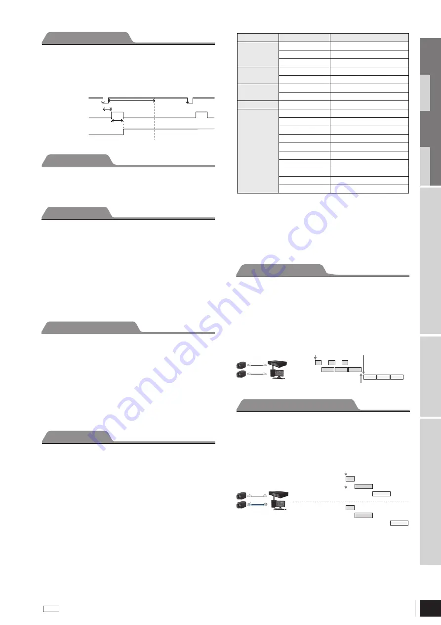
The trigger signals can be accepted during the sensor readout
signals are asserted.
If the trigger cycle overs the maximum value of the frame rate,
images are distorted.
Set FastTriggerMode to OFF for XCG-CG160/CG160C and XCG-
CG510/CG510C.
Trigger signal
Exposure
Sensor readout signal
EXP
(Sensor output)
Trigger latency
Trigger input inhibition
Main set values can be saved to the channels 1 to 16 of USERSET.
User set is available during special trigger mode (Bulk Trigger/
Sequential Trigger).
Manual gain
The manual gain can be finely set in 0.1 dB units or bit levels.
Although the settable lower/upper limit values of the gain are
slightly different in each camera, the gain parameter value can be
set from –1 dB or less to 27 dB or more.
Auto gain (AGC)
By setting AUTOGAIN, the gain is automatically adjusted according
to the image pickup environment.
AGC works so that the average level in a detection frame may
reach AGC-LEVEL. The AGC detection frame is set to the central
region by default. The detection frame can be displayed or the
detection area changed.
User Set
Gain
Auto frame rate
The reading cycle is set to allow the frame rate to be the maximum
value automatically according to the current shutter setting and the
partial scan setting in the free-run operation (Shutter has priority).
The next exposure is performed while outputting a video and the
next video output is started immediately after finishing all video
outputs. The frame rate is lowered when setting the shutter time
longer than the video output time.
Specifying frame rate
The frame rate of the video output can be specified in the free-run
operation. The value of the frame rate [fps] should be entered. The
frame rate faster than the fastest frame rate cannot be set.
Frame Rate Control
Overlap trigger
Memory shot is a function that controls the exposure timing and
image output to the network individually.
This is effective when multiple cameras are connected to the
same network and it is necessary to expose them at the same
time in a configuration that exceeds 1 Gbps band when operated
simultaneously.
Memory shot is available in multi-frame mode or single-frame
mode.
Number of images that can be saved is determined by image size
and pixel format.
Normally, images are sequentially output when exposure ends, but
the image output start timing can be delayed.
Optimal when requiring simultaneous exposure, but there are
several cameras connected to the same network and the
configuration makes the bandwidth exceed 1Gbps when operated
simultaneously.
Optimal when shooting 1 shot with single frame or trigger.
Memory shot
Exposure
Imager readout
Camera output
Exposure start
Sending of command
Reached the specified amount Event issued
Output timing control
Cam1
Cam2
Exposure
Imager readout
Camera output
Exposure
Imager readout
Camera output
Setting example:
The strobe control signal is output to GPO2 (DC IN connector 3rd pin)
by Hi active setting.
LineSelector = 1
LineMode = 1
LineInverter = 0
LineSource = 3
Register
Parameter
Setting
LineSelector
Line 1 (0)
DC IN connector 2nd pin
Line 2 (1)
DC IN connector 3rd pin
Line 3 (2)
DC IN connector 4th pin
LineMode
Input (0)
Set to output
Output (1)
Input setting
LineInverter
Off (0)
Without output inversion
On (1)
With output inversion
LineStatus
Input signal level
LineSource
TriggerThrough (0)
Trigger through signal
ExposureActive (2)
Exposure signal
StrobeActive (3)
Strobe control signal
SensorReadout (4)
Sensor readout signal
UserOutput 1 (5)
User definition 1
UserOutput 2 (6)
User definition 2
UserOutput 3 (7)
User definition 3
SignalTrue (8)
Level H
SignalFalse (9)
Level L
PWM (10)
Pulse generation signal
GPIO
GPI
The signal level which is input in the 2nd, 3rd, and 4th* DC IN
connector can be detected. After selecting a connector by
LineSelector register, the signal level is acquired from LineStatus
register.
* Only output is available for XCG-CG160/CG160C
GPO
Various signals can be output from the 3rd and 4th DC IN
connector. After selecting a connector by LineSelector register
and setting LineMode to Output, LineSource is set. The output
polarity is set by LineInverter register.


