


3-12
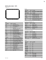
WRR-802A (U)
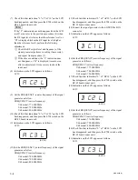
(6) Set the channel setting and FREQUENCY (carrier
frequency) of the signal generator as shown
1
and
2
below.
Perform the procedures (2) through (5) above, for each
channel setting (
1
and
2
).
1
Channel setting:
U64 model: Group 00, 6401 channel (770.125 MHz)
U66 model: Group 00, 6601 channel (782.125 MHz)
U68 model: Group 00, 6801 channel (794.125 MHz)
Signal generator setting:
FREQUENCY(Carrier frequency)
U64 model : 770.125 MHz
U66 model : 782.125 MHz
U68 model : 794.125 MHz
2
Channel setting:
U64 model : Group 00, 6547 channel (781.875 MHz)
U66 model : Group 00, 6747 channel (793.875 MHz)
U68 model : Group 00, 6947 channel (805.875 MHz)
Signal generator setting:
FREQUENCY (Carrier frequency)
U64 model: 781.875 MHz
U66 model: 793.875 MHz
U68 model: 805.875 MHz
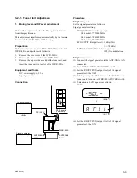
6. AF level indicator/AF indicator check
Procedure
(1) Set the WRR-802A as follows;
Channel setting:
U64 model; Group 00, 6501 channel (776.125 MHz)
U66 model; Group 00, 6701 channel (788.125 MHz)
U68 model; Group 00, 6901 channel (800.125 MHz)
VOL. control: Any position
Muting: OFF
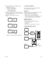
(2) Connect the signal generator to the ANTENNA A IN
connector.
(3) Set the signal generator as follows:
Signal generator setting
FREQUENCY(carrier frequency)
U64 model; 776.125 MHz
U66 model; 788.125 MHz
U68 model; 800.125 MHz
RF OUTPUT (Output level): 60 dB
u
V
EMF
(=
_
53 dBm)
MODULATION (Modulation frequency): 1 kHz
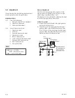
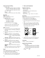
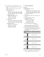
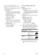
(4) Increase gradually DEVIATION (frequency deviation)
of the signal generator starting from
±
3 kHz, and
check that the deviation of the signal generator is
±
(5.0
±
1.0) kHz with the AF indicator as follows.
DEVIATION setting
AF indicator
on signal generator
±
(5.0
±
1.0) kHz
AF level indicator (LCD):
Lights.
AF indicator (LED):
Lights.
Less than
AF level indicator (LCD):
±
(5.0
±
1.0) kHz
Goes out.
AF indicator (LED):
Goes out.
(5) Connect the signal generator to the ANTENNA B IN
connector, and perform the procedures (3) and (4)
above.
AF
AF