


3-5
WRR-802A (U)
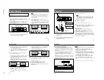
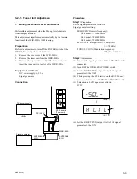
(22) Set the FREQUENCY (carrier frequency) of the
signal generator as follows;
FREQUENCY (carrier frequency)
U64 model; 780.000 MHz
U66 model; 792.000 MHz
U68 model; 804.000 MHz
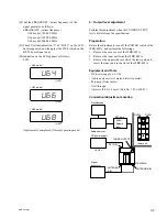
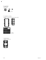
(23)Check first that indication “L” of “BC3L” on the LCD
has disappeared, and then press the S708 switch on the
RF-92 board (tuner unit).
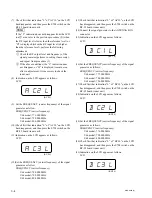
(24)Indication on the LCD appears as follows:
LCD:
Adjustment is completed. (Normal operation mode)
U64
(U64)
U66
(U66)
U68
(U68)
• U64 model
• U66 model
• U68 model
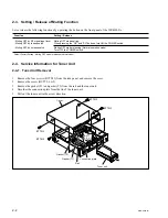
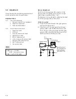
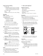
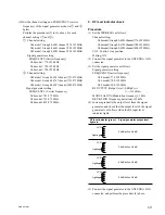
2. Output level adjustment
Perform this adjustment when the TUNER OUTPUT
levels deviate from the specification.
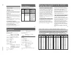
Preparation
Before the adjustments, turn off the POWER switch of the
WRR-802A, and perform the followings.
1.
Remove the case cover of the WRR-802A.
2.
Remove the tuner unit from the WRR-802A.
3.
Remove the upper side case lid of the tuner unit, and
insert the tuner unit to the slot of the WRR-802A.
Equipment and Tools
.
DC power supply:
+
9 Vdc
.
Audio analyzer (level meter, distortion meter)
.
Mic amp (Noise meter)
.
Oscilloscope
.
Adjuster (0.4
x
1.3 mm): (Part No. 7-221-652-81)
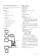
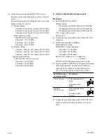
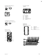
Connection/Adjustment Location
Oscilloscope
MIC amp
600
Z
balance
input
Audio analyzer
+
9 Vdc
DC power supply
DC IN 9 V
Signal
generator
WRR-802A
ANTENNA B IN
ANTENNA
A IN
TUNER OUTPUT
RV202
RV201
Tuner unit