


3-6
WRR-802A (U)
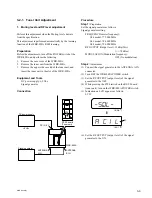
Switch and Control Setting
Channel setting:
U64 model; Group 00, 6501 channel (776.125 MHz)
U66 model; Group 00, 6701 channel (788.125 MHz)
U68 model; Group 00, 6901 channel (800.125 MHz)
VOL. control: MAX
Muting:
OFF
TUNER OUTPUT LEVEL switch: LINE (
_
20 dBm)
Procedure
Step 1:
Preparation
Set the signal generator as follows:
Signal generator setting
FREQUENCY(carrier frequency)
U64 model; 776.125 MHz
U66 model; 788.125 MHz
U68 model; 800.125 MHz
RF OUTPUT (Output level): 60 dB
u
V
EMF
(=
_
53 dBm)
MODULATION (Modulation frequency): 1 kHz
DEVIATION (Frequency deviation):
±
5 kHz
Step 2:
Adjustment
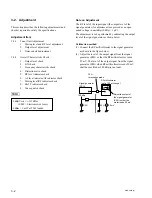
(1) Connect the audio analyzer to the TUNER OUTPUT
(XLR type) connector via MIC amp (Amplification
gain 0 dB).
(2) Connect the signal generator to the ANTENNA A IN
connector.
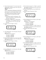
(3) Adjustment (ANTENNA A IN side adjustment)
Specification: Output level (level meter indication
level) =
_
21 dBm
±
0.5 dB (at 600
Z
loaded)
Adjustment:
1
RV202/RF-92 board (Tuner unit)
(4) Connect the signal generator to the ANTENNA B IN
connector.
(5) Adjustment (ANTENNA B IN side adjustment)
Specification: Output level (level meter indication
level) =
_
21 dBm
±
0.5 dB (at 600
Z
loaded)
Adjustment:
1
RV201/RF-92 board (Tuner unit)
n
The output level difference between the ANTENNA A
side and the ANTENNA should be within 0.3 dB.
Step 3:
After completing adjustment, turn off the WRR-802A
power switch and perform the followings.
(1) Remove the tuner unit from the WRR-802A.
(2) Attach the upper side case lid to the tuner unit, and
insert the tuner unit to the slot of the WRR-802A.
3. Noise squelch adjustment
Equipment and Tools
.
DC power supply:
+
9 Vdc
.
Signal generator
.
Audio analyzer (level meter, distortion meter)
.
Mic amp (Noise meter)
.
Oscilloscope
.
Adjuster (0.4
x
1.3 mm) : (Part No. 7-221-652-81)
Preparation
Before the adjustments, turn off the POWER switch of the
WRR-802A, and perform the followings.
1.
Remove the case cover of the WRR-802A.
2.
Remove the tuner unit from the WRR-802A.
3.
Remove the upper and lower side case lids of the tuner
unit.
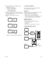
4.
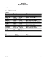
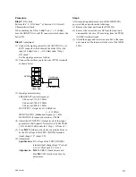
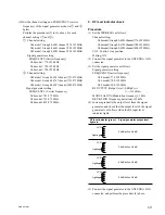
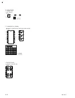
Solder a wire (80 mm long) to the TP201(NOISE)
terminal (land) on the RF-92 board (tuner unit), and
take out the free side of the wire (80 mm long) to the
upper side of the tuner unit as below.
5.
Attach the lower side case lid to the tuner unit, and
insert the tuner unit to the slot of the WRR-802A.
Connection
Same as “ 2. Output level adjustment ”.
Switch and Control Setting
Channel setting:
U64 model; Group 00, 6501 channel (776.125 MHz)
U66 model; Group 00, 6701 channel (788.125 MHz)
U68 model; Group 00, 6901 channel (800.125 MHz)
VOL. Control: MAX
Muting:
OFF
TP201(NOISE)
terminal(land)
Tuner unit
(Lower side)
Solder
RF-92 Board
Lead wire
(80 mm long)
Tuner unit
(Upper side)
Lead wire