


3-7
WRR-802A (U)
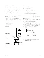
Procedure
Step 1:
S/N check
Perform the “ 2. S/N Check ” of Section 3-2-2. Overall
Characteristics Check.
When checking the S/N at 0 dB
u
V
EMF
( =
_
113 dBm) ,
note the ANNTENA A or B IN connector which shows the
better S/N.
Step 2:
Adjustment
(1) Connect the signal generator to the ANTENNA A (or
B) IN connector which showed the better S/N at the
input of 0 dB
u
V
EMF
( =
_
113 dBm) under “Step 1.
S/N check”.
Set the signal generator as follows;
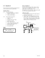
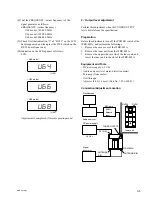
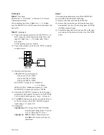
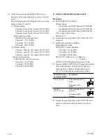
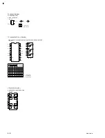
(2) Connect the oscilloscope to the wire (TP201 terminal)
as shown below.
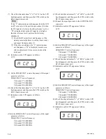
(3) Signal generator setting
FREQUENCY(carrier frequency)
U64 model; 776.125 MHz
U66 model; 788.125 MHz
U68 model; 800.125 MHz
RF OUTPUT (Output level): 0 dB
u
V
EMF
(=
_
113 dBm)
MODULATION (Moduation frequency): 1 kHz
DEVIATION (Frequency deviation):
±
5 kHz
(4) Adjust the RF OUTPUT (Output level) of the signal
generator so that Signal to Noise ratio is 34 dB
±
5 dB
( S/N; 34 dB
±
5 dB) under the “ Step 1. S/N check ”.
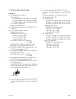
(5) Turn
1
RV205(tuner unit) slowly counterclockwise to
be the DC voltage of the TP201 (NOISE) terminal
(land) change “L” (about 0 V).
(6) Adjustment
Specification: DC voltage of the TP201 (NOISE)
terminal(land) change from “L”(about
0 V) to “H”(about 4.8 V) level.
Adjustment:
1
RV205/RF-92 board (tuner unit)
Turn
1
RV205 slowly clockwise for
adjustment.
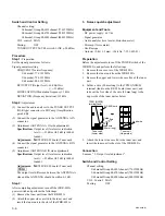
Step 3.
After completing adjustment, turn off the WRR-802A
power switch and perform the followings.
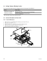
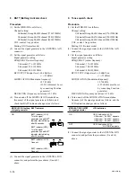
(1) Remove the tuner unit from the WR-802A.
(2) Remove the lower side case lid from the tuner unit,
and unsolder the wire ( 80 mm long) from the TP201
(NOISE) terminal (land).
(3) Attach the upper and lower side case lids to the tuner
unit, and insert the tuner unit to the slot of the WRR-
802A.
RV205
Oscilloscope
DC range setting
Tuner unit
(Upper side)