1-10
UP-55MD
Mechanical main
unit assembly
BVTT
2.6
x
5
BVTT
2.6
x
5
Ribbon drive assembly
SU-87 board
Harnesses
SU-86 board
PS3
x
4
Ribbon lock
Ribbon lock
Ribbon lock
spring
Supply
lock
Supply lock
Supply lock
spring
W2.3
W2.3
W2.3
W3
W3
W2.3
Ribbon gear
Ribbon gear
Idler gear (R)
Idler gear (R)
Worm wheel (R)
Worm wheel (R)
Limiter (S)
assembly
Limiter (T)
assembly
Limiter (S) assembly
Limiter (T)
assembly
DC motor (ribbon)
subassemblies
DC motor (ribbon) subassemblies
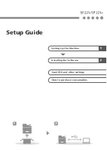
1-5-4. Ribbon Drive Assembly
1.
Remove the top cover. (Refer to Section 1-3-1.)
2.
Remove the front panel assembly.
(Refer to Section 1-3-2.)
3.
Remove the MA-142 board. (Refer to Section 1-4-1.)
4.
Remove the mechanical main unit assembly.
(Refer to Section 1-5-2.)
5.
Remove the four screws, then remove the ribbon drive
assembly.
6.
Disconnect the two harnesses from the connectors on
the SU-86 board and SU-87 board.
7.
Remove the two retaining rings (W2.3) and the
retaining ring (W3.0), then remove the idler gear (R),
worm wheel (R) and limiter (S) assembly.
8.
Remove the four screws, then remove the two DC
motor (ribbon) subassemblies.
9.
Remove the retaining ring (W2.3), then remove the
ribbon lock and ribbon lock spring.
10. Remove the retaining ring (W2.3), then remove the
supply lock and supply lock spring.
11. Remove the retaining ring (W3.0), then remove the
ribbon gear.
12. Remove the retaining ring (W2.3), then remove the
limiter (T) assembly.
13. Attach the ribbon drive assembly in the reverse order
of steps 1 to 12.
Summary of Contents for UP55MD
Page 1: ...COLOR VIDEO PRINTER UP 55MD SERVICE MANUAL Volume 1 1st Edition Revised 2 ...
Page 4: ......
Page 8: ......
Page 30: ......
Page 38: ......
Page 48: ......
Page 52: ......
Page 72: ......
Page 74: ...Sony Corporation 2010 7 08 2005 UP 55MD SY E 9 879 778 03 ...