— 8 —
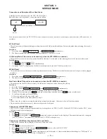
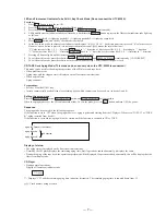
• When operations end abnormally:
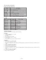
Display of fluorescent display tube
Display of Operations
Operation
TAPE A AG-1
TAPE A AG-2
TAPE A AG-3
TAPE A AG-4
TAPE A AG-5
TAPE B AG-1
TAPE B AG-2
TAPE B AG-3
TAPE B AG-4
TAPE B AG-5
TAPE A REW
TAPE A FWD
TAPE A FF
TAPE A REV
TAPE A REW
TAPE B REW
TAPE B FWD
TAPE B FF
TAPE B REV
TAPE B REW
Timing of Ending
Shutoff
2 minute playback
20 seconds or shutoff
2 minutes playback
Shutoff
Shutoff
2 minute playback
20 seconds or shutoff
2 minute playback
Shutoff
Operations during aging
• Operations are performed in the following sequence during aging.
<CD player>
1.
The CD tray rotates and disc 1 is selected.
2.
Chucking is performed.
3.
TOC is read.
4.
Track 1 played back for 2 seconds.
5.
The last track is played back for 2 seconds.
6.
1 to 5 is repeated.
7.
After 12 minutes of aging, aging is switched to the tape deck.
<Tape Deck>
1.
The tape in deck A is rewound to the head.
2.
The FWD side is played back for 2 minutes.
3.
The tape is fast forwarded (FF) for 20 seconds. The following procedure is performed when the tape end is reached before the 20
seconds.
4.
The REV side is played back for 2 minutes.
5.
The tape is rewound to the head (REW).
6.
The tape in deck B is rewound to the head.
7.
The FWD side is played back for 2 minutes.
8.
The tape is fast forwarded (FF) for 20 seconds. The following procedure is performed when the tape end is reached before the 20
seconds.
9.
The REV side is played back for 2 minutes.
10. The tape is rewound to the head (REW).
11. Aging is switched to the CD player.
Display
Main Cause
NO DISC ERR
FOCUS1 ERR
FOCUS2 ERR
GFS ERR
FBIAS ERR
SENSOR ERR
TABLE ERR
TRAY ERR
DISC 1 is NO DISC from the beginning
Focus is not imposed properly
The focus deviated several times after the disc rotated normally
GFS ERROR
Error during focus bias adjustment
DISC 1 was found to be NO DISC by the disc sensor
The table did not rotate normally
The tray containing the BD did not operate normally
Tape Deck
Summary of Contents for STR-W777
Page 26: ...5 10 SCHEMATIC DIAGRAM AV MIC SECTION Refer to page 58 for IC Block Diagrams 35 ...
Page 27: ...5 11 Printed Wiring Board AV MIC Section Refer to page 12 for Circuit Boards Location 36 ...
Page 28: ...STR W777 5 12 SCHEMATIC DIAGRAM POWER AMP SECTION 37 38 ...
Page 30: ...STR W777 5 14 SCHEMATIC DIAGRAM DISPLAY SECTION Refer to page 59 for IC Block Diagrams 41 42 ...
Page 34: ...STR W777 5 18 SCHEMATIC DIAGRAM SURROUND AMP SECTION 49 50 ...
Page 37: ... 55 5 21 SCHEMATIC DIAGRAM TRANS SECTION STR W777 ...


