— 60 —
• Abbreviation
FL : Fluorescent indicator tube
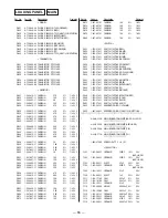
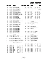
5-23. IC PIN FUNCTION
• IC501 SYSTEM CONTROL (uPD780016AYGF-012-3BA)
Pin No.
1
2
3
4
5
6
7
8
9
10
11
12
13
14
15
16
17
18
19
20
21
22
23
24
25
26
27
28
29
30
31
32
33
34
35
36
37
38
39
40
I/O
O
O
O
O
O
O
O
—
—
O
I
—
O
I
I
I
I
I
I
I
I
O
—
—
I
I
I
I
I
I
I
I
—
—
O
O
O
O
—
—
Description
Not used
Surround level A signal output
Surround level B signal output
Not used
DBFB level 2 signal output
DBFB level 1 signal output
Mute signal output
Ground
Test terminal (Connected to ground)
X’ tal (5MHz)
Power supply (+5V)
X’ tal (32kHz)
Reset signal input
RDS clock input
RDS data input
Rotary encoder (VOLUME) pulse input
Rotary encoder (MULTI JOG STATION) pulse input
Spectrum analyzer control output
Power supply (+5V)
Analog power supply (+5V)
Audio input for VACS control
Spectrum analyzer data input
Key data input
Back up signal input
Analog ground
Ground
FL data output
FL clock output
FL latch output
FL reset output
Ground
Ground
Pin Name
CLK
LEVEL A
LEVEL B
PROLOGIC RLY
DBFB B2
DBFB B1
TA MUTE
GND
TEST
X2
X1
VDD
XT2
XT1
RESET
RDS CLK
RDS DATA
VOL A
VOL B
JOG A
JOG B
SPEANA CONT
VDD
A VDD
VACS
SPEANA0
SPEANA1
KEY0
KEY1
KEY2
KEY3
ACCUT
A VSS
GND
FL DATA
FL CLK
FL LAT
FL RESET
GND
VSS
Summary of Contents for STR-W777
Page 26: ...5 10 SCHEMATIC DIAGRAM AV MIC SECTION Refer to page 58 for IC Block Diagrams 35 ...
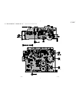
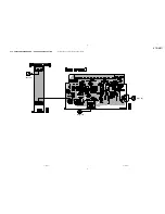
Page 27: ...5 11 Printed Wiring Board AV MIC Section Refer to page 12 for Circuit Boards Location 36 ...
Page 28: ...STR W777 5 12 SCHEMATIC DIAGRAM POWER AMP SECTION 37 38 ...
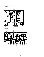
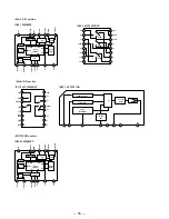
Page 30: ...STR W777 5 14 SCHEMATIC DIAGRAM DISPLAY SECTION Refer to page 59 for IC Block Diagrams 41 42 ...
Page 34: ...STR W777 5 18 SCHEMATIC DIAGRAM SURROUND AMP SECTION 49 50 ...
Page 37: ... 55 5 21 SCHEMATIC DIAGRAM TRANS SECTION STR W777 ...


