— 3 —
TABLE OF CONTENTS
1. GENERAL
........................................................................... 4
2. DISASSEMBLY
• Sliding Panel Assembly ...................................................... 5
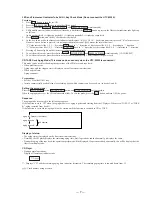
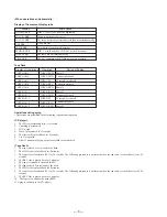
3. SERVICE MODE
.............................................................. 6
4. ELECTRICAL ADJUSTMENT
................................... 11
5. DIAGRAMS
5-1.
Circuit Boards Location ··················································· 12
5-2.
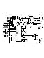
Block Diagrams
• Tuner Section (AEP, UK model) ···································· 13
• Tuner Section (East European, CIS model) ··················· 15
• Main Section ·································································· 17
• Power Section ································································ 19
5-3.
Schematic Diagram
–Tuner (AEP, UK model) Section – ································· 23
5-4.
Printed Wiring Board
–Tuner (AEP, UK model) Section – ································· 25
5-5.
Printed Wiring Board
–Tuner (East European, CIS model) Section – ················ 26
5-6.
Schematic Diagram
–Tuner (East European, CIS model) Section – ················ 27
5-7.
Printed Wiring Board – Main Section – ··························· 29
5-8.
Schematic Diagram – Main (1/2) Section – ····················· 31
5-9.
Schematic Diagram – Main (2/2) Section – ····················· 33
5-10. Schematic Diagram – AV/Mic Section – ·························· 35
5-11. Printed Wiring Board – AV/Mic Section – ······················· 36
5-12. Schematic Diagram – Power Amp Section – ··················· 37
5-13. Printed Wiring Board – Power Amp Section – ················· 39
5-14. Schematic Diagram – Display Section – ·························· 41
5-15. Printed Wiring Board – Display Section – ······················· 43
5-16. Schematic Diagram – Sliding Panel Section – ················· 45
5-17. Printed Wiring Board – Sliding Panel Section – ·············· 47
5-18. Schematic Diagram – Surround Section – ······················· 49
5-19. Printed Wiring Board – Surround Section – ····················· 51
5-20. Printed Wiring Board – Trans Section – ··························· 53
5-21. Schematic Diagram – Trans Section – ····························· 55
5-22. IC Block Diagrams ··························································· 56
5-23. IC Pin Function ································································ 60
6. EXPLODED VIEWS
6-1.
Case and Sliding Panel Section ........................................ 63
6-2.
Front Panel Section .......................................................... 64
6-3.
Slide Mechanism Section ................................................. 65
6-4.
Circuit Boards and Back Panel Section ............................ 66
7. ELECTRICAL PARTS LIST
........................................ 67
SAFETY-RELATED COMPONENT WARNING !!
COMPONENTS IDENTIFIED BY MARK
!
OR DOTTED LINE
WITH MARK
!
ON THE SCHEMATIC DIAGRAMS AND IN
THE PARTS LIST ARE CRITICAL TO SAFE OPERATION.
REPLACE THESE COMPONENTS WITH SONY PARTS
WHOSE PART NUMBERS APPEAR AS SHOWN IN THIS
MANUAL OR IN SUPPLEMENTS PUBLISHED BY SONY.
LABEL MODEL NUMBER
No.
MODEL IDENTIFICATION
— BACK PANEL —
Saudi Arabia, Singapore, Malaysia
4-900-848-2
π
Thai, Australian
4-900-848-3
π
AEP, UK, East European, CIS
4-900-848-4
π
MODEL
PART No.
Summary of Contents for STR-W777
Page 26: ...5 10 SCHEMATIC DIAGRAM AV MIC SECTION Refer to page 58 for IC Block Diagrams 35 ...
Page 27: ...5 11 Printed Wiring Board AV MIC Section Refer to page 12 for Circuit Boards Location 36 ...
Page 28: ...STR W777 5 12 SCHEMATIC DIAGRAM POWER AMP SECTION 37 38 ...
Page 30: ...STR W777 5 14 SCHEMATIC DIAGRAM DISPLAY SECTION Refer to page 59 for IC Block Diagrams 41 42 ...
Page 34: ...STR W777 5 18 SCHEMATIC DIAGRAM SURROUND AMP SECTION 49 50 ...
Page 37: ... 55 5 21 SCHEMATIC DIAGRAM TRANS SECTION STR W777 ...


