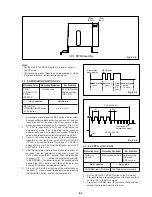
6-9
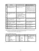
No.
Mode of VCR
AUDIO OUTPUT
AUDIO OUTPUT
(Indicator Panel)
Lch
Rch
1
STEREO
300Hz
approx.
300Hz
approx.
(“ ST ” indicator lights)
sine
240 mVp-p
sine
15 mVp-p
wave
wave
2
MONO
300Hz
approx.
300Hz
approx.
(NO indicators)
sine
120 mVp-p
sine
120 mVp-p
wave
wave
3
SAP
300Hz
approx.
300Hz
approx.
(“ SAP ” indicator lights)
sine
120 mVp-p
sine
180 mVp-p
wave
wave
4
SAP
300Hz
approx.
(“ SAP ” indicator lights)
–
sine
180 mVp-p
wave
7. Set the TV multichannel sound generator (STEREO switch :
Lch, INT FREQ switch : 3 kHz), and confirm that the
difference between the AUDIO OUTPUT terminal (L)
and (R) is more than 25 dB.
8. Set the TV multichannel sound generator (STEREO switch :
Rch, INT FREQ switch : 300 Hz), and confirm that the
difference between the AUDIO OUTPUT terminal (L)
and (R) is more than 20 dB. If not, repeat steps 5 to 8.
Note : Measurement of steps 5 through 8, be sure to
connect the BPF between oscilloscope and AUDIO
OUTPUT terminals.
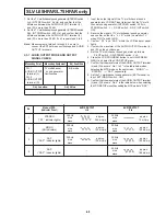
2-3-7. AUDIO OUTPUT MODE AND OUTPUT
SIGNAL CHECK
1. Input the output signal of the TV multichannel sound
generator into VCR ANT input terminal. Set the TV multi-
channel sound generator (INT FREQ switch : 300 Hz,
STEREO switch : L + R, SAP switch : ON, PILOT switch :
ON).
2. Receive the signal of TV multichannel sound generator,
and confirm so that the “ L + R ” within the monitor TV
when PILOT switch to ON.
3. Confirm “ ST ” and “ SAP ” within the VCR indicator panel
lights.
4. Confirm the waveform of the AUDIO OUTPUT terminal (L)
and (R) on the oscilloscope.
5. Set the TV multichannel sound generator as follows.
PILOT switch : ON, STEREO switch : Lch.
6. Press the VCR PROGRAM button to set ON-SCREEN
MENU, and select the VCR SETUP menu.
7. Confirm that the waveforms of the AUDIO OUTPUT terminal
(L) and (R) become “ No. 1 to 3 ” in the table below when
selecting the MTS mode on the next screen, “ MONO ”
n
“ STEREO ”
n
“ SAP ” sequentially.
8. Set the TV multichannel sound generator (EXT terminal : no
input, EXT (MONO) switch : ON).
9. Confirm that the waveforms of the AUDIO OUTPUT terminal
(L) and (R) become “ No.4 ” in the table below when selecting
the VCR SETUP menu then setting the MTS mode to “ SAP ”.
Measuring Point
Measuring Equipment
Adj. Condition
CH : 1
TV multichannel
E-E mode
AUDIO OUTPUT sound generator
terminal (L)
Oscilloscope
CH : 2
AUDIO OUTPUT
terminal (R)
Adj. Location
Adj. Value
–
–
SLV-L65HFAR/L75HFAR only
Summary of Contents for SLV-L45AR
Page 6: ...1 2 ...
Page 7: ...1 3 ...
Page 8: ...1 4 ...
Page 9: ...1 5 ...
Page 10: ...1 6 ...
Page 11: ...1 7 ...
Page 12: ...1 8 E ...
Page 17: ...3 2 MECHANISM CONNECTION DIAGRAM ...
Page 18: ...3 3 3 4 SLV L45AR L65HFAR L75HFAR OVERALL WIRING DIAGRAM SLV L45AR ...
Page 19: ...SLV L45AR L65HFAR L75HFAR OVERALL WIRING DIAGRAM SLV L65HFAR L75HFAR 3 5 3 6 ...
Page 20: ...3 7 3 8 SLV L45AR L65HFAR L75HFAR SYSTEM CONTROL SERVO CIRCUIT DIAGRAM SLV L45AR ...
Page 21: ...3 9 3 10 SLV L45AR L65HFAR L75HFAR SYSTEM CONTROL SERVO CIRCUIT DIAGRAM SLV L65HFAR L75HFAR ...
Page 25: ...SLV L45AR L65HFAR L75HFAR 4 3 4 4 CP 1 BOARD VA A VIDEO AUDIO TUNER CIRCUIT DIAGRAM SLV L45AR ...
Page 33: ...4 19 4 20 CP 1 BOARD SY A SYSTEM CONTROL SERVO CIRCUIT DIAGRAM SLV L65HFAR L75HFAR ...


