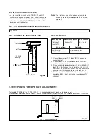
5-27
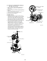
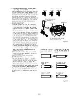
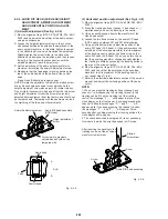
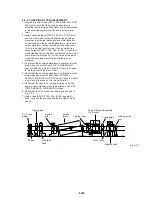
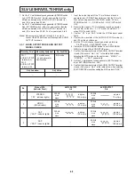
4-3-3. GUIDE ROLLER HEIGHT ADJUSTMENT
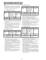
(See Figs. 4-3-3 and 4-3-4)
1) Play the Alignment Tape (NTSC: KRV-52NE, PAL: KRV-
52PL) and check that the envelope waveform is at its
maximum at the tracking centre. Then, after loosening
the S guide roller and the T guide roller by rotating them
anticlockwise, tighten them in turn until the envelope
waveform becomes flat. If the envelope waveform is not
at its maximum at the tracking centre, refer to section 4-
3-4 and carry out a rough adjustment of the horizontal
position of the audio R/P head (ACE head) before
adjusting the guide rollers.
2) Adjust the S guide roller.
1
Press the tracking button (Channel – ), and check
whether, when the envelope waveform has reached
50% of its maximum, the front half of the envelope
waveform is flat. If not, fine-tune the S guide roller as
follows.
a. If the front half of the envelope waveform is as shown
in Fig. 4-3-4 (a), this means that you have pressed the
S guide roller too far. Therefore, loosen it slightly, and
when it is in the state shown in Fig. 4-3-4 (b), tighten it
again, stopping when the envelope waveform is flat.
b. If the front half of the envelope waveform is as shown
in Fig. 4-3-4 (b), this means you have not pressed the
S guide roller far enough. Therefore, tighten it slightly,
stopping when the envelope waveform becomes flat.
c. If the front half of the envelope waveform is as shown
in Fig. 4-3-4 (c), it may happen that when you tighten
the S guide roller, the wrapper waveform does not
disappear, but sinks into the flat part, as shown in Fig.
4-3-4 (d). If this happens, the status shown in Fig. 4-3-
4 (c) is normal, so loosen the S guide roller, then
tighten it again until the envelope waveform is as
shown in Fig. 4-3-4 (c).
2
Check that at the tracking centre, the output of the
front half of the envelope waveform is not less than
80% of the maximum.
3
Rotate the S guide roller 20
°
anticlockwise.
3) AdjusttheTguide roller.
1
press the tracking button (channel – ) and check
whether, when the envelope waveform is 50% of
maximum, the back half of the envelope waveform is
flat. If not, loosen the T guide roller slightly, then
tighten it gradually until the back half of the envelope
waveform becomes flat.
2
Check that the output for the back half of the envelope
waveform is at its maximum at the tracking centre.
4) Check that the envelope waveform does not fluctuate
when you switch from F-SEARCH to PLAY or from R-
SEARCH to PLAY. If it does fluctuate, repeat steps 3)
and 4).
Normal
Pressed
too far
Not pressed
far enough
Eccentric screwdriver
(J-6082-044-A)
S guide roller
T guide roller
Do not touch
the fixed
screw
The tape should not pass along
the cylinder lead surface
Fig. 4-3-3
If the envelope waveform
is at maximum at the
tracking centre, adjust to
flat.
In normal status, the waveform
will be flat even when the
envelope waveform is reduced
to 50%.
100%
50%
50%
50%
50%
50%
(a) S guide roller
pressed too far
(d) S guide roller
pressed too far
(b) S guide roller not
pressed far enough
(c) Normal status for
wrapper waveform
Fig. 4-3-4
Summary of Contents for SLV-L45AR
Page 6: ...1 2 ...
Page 7: ...1 3 ...
Page 8: ...1 4 ...
Page 9: ...1 5 ...
Page 10: ...1 6 ...
Page 11: ...1 7 ...
Page 12: ...1 8 E ...
Page 17: ...3 2 MECHANISM CONNECTION DIAGRAM ...
Page 18: ...3 3 3 4 SLV L45AR L65HFAR L75HFAR OVERALL WIRING DIAGRAM SLV L45AR ...
Page 19: ...SLV L45AR L65HFAR L75HFAR OVERALL WIRING DIAGRAM SLV L65HFAR L75HFAR 3 5 3 6 ...
Page 20: ...3 7 3 8 SLV L45AR L65HFAR L75HFAR SYSTEM CONTROL SERVO CIRCUIT DIAGRAM SLV L45AR ...
Page 21: ...3 9 3 10 SLV L45AR L65HFAR L75HFAR SYSTEM CONTROL SERVO CIRCUIT DIAGRAM SLV L65HFAR L75HFAR ...
Page 25: ...SLV L45AR L65HFAR L75HFAR 4 3 4 4 CP 1 BOARD VA A VIDEO AUDIO TUNER CIRCUIT DIAGRAM SLV L45AR ...
Page 33: ...4 19 4 20 CP 1 BOARD SY A SYSTEM CONTROL SERVO CIRCUIT DIAGRAM SLV L65HFAR L75HFAR ...

