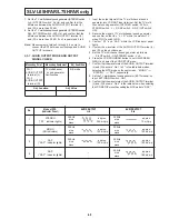
6-8
Measuring Point
Measuring Equipment
Adj. Condition
CH : 1
TV multichannel
E-E mode
AUDIO OUTPUT sound generator
terminal (L)
Oscilloscope
CH : 2
Band path filter
AUDIO OUTPUT (200 Hz ~ 15kHz)
terminal (R)
Adj. Location
Adj. Value
VR632 (SEP. LOW)
Minimum level (less than
VR634 (SEP. HIGHT)
15mVp-p)
Notes:
• Set the INPUT switch on the remote control to TUNER.
• Set the VIF/RF OUTPUT switch on the TV Multichannel
Sound Generator to CH-3 or CH-4. And LEVEL volume
control to push (locked the RF output level).
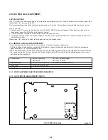
2-3-3. STEREO/SAP FILTER ADJ.
Measuring Point
Measuring Equipment
Adj. Condition
TP633
Standard audio
Disconnected
signal generator (SG)
Power cord of
Oscilloscope
VCR
Frequency counter
DC power supply unit
Adj. Location
Adj. Value
VR633 (ST.DBX FIL)
Minimum level (Less than 10 mVp-p)
1. Temporary disconnect the power cord of the VCR to set
the power OFF.
2. Apply 5V(DC) to TP630 from the DC power supply unit.
3. Connect the standard audio signal generator and
frequency counter to TP631, and input 22.9 kHz
±
50
Hz, –10
±
1 dBM sine wave.
4. After confirming TP633 output on the oscilloscope,
adjust VR633 (ST. DBX FIL) so that the output is
brought to its minimum level (less than 10 mVp-p).
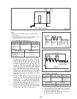
2-3-4. STEREO VCO ADJ.
Measuring Point
Measuring Equipment
Adj. Condition
TP635
TV multichannel
E-E mode
sound generator
DC voltmeter
Adj. Location
Adj. Value
VR635 (VCO)
–
1. Input the output signal of the TV multichannel sound
generator into the VCR ANT input terminal.
2. Set the TV multichannel sound generator as follows.
SAP switch : OFF, INT FREQ switch : 300 Hz,
STEREO switch : L + R, VIF/RF OUTPUT : CH-3 or CH-4.
3. Receive the signal of TV multichannel sound generator.
and confirm so that the “ L + R ” within the monitor TV
when PILOT switch to ON.
4. Set OFF the pilot switch of the TV multichannel sound
generator, then measure the DC output voltage of
TP635 and write the value down.
5. Set ON the pilot switch and confirm that “ ST ” within
the indicator panel lights. If not, adjust VR635 (VCO)
until “ ST ” lights.
6. Measure the output voltage of TP635, and adjust
VR635 (VCO) so that the output voltage agree with the
value (within
±
0.03 V) measured in step 3.
2-3-5. INPUT LEVEL ADJ.
1. Input the output signal of the TV multichannel sound
generator into the VCR ANT input terminal.
2. Set the TV multichannel sound generator as follows.
SAP switch : OFF, EXT (MONO) switch : ON.
3. Input 300
±
50 Hz sine wave into the EXT INPUT terminal
of the TV multichannel sound generator from the standard
audio signal generator.
4. Connect the AC voltmeter to the EXT INPUT terminal, and
adjust the output level of the standard audio signal
generator so that the input voltage becomes 343.7
±
1
mVrms (terminated at 600
Ω
).
5. Adjust the VR631 (INPUT LEVEL) so that the AC voltme-
ter connected to TP631 becomes 100
±
5mVrms.
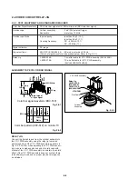
2-3-6. SEPARATION ADJ.
Measuring Point
Measuring Equipment
Adj. Condition
TP631
TV multichannel
E-E mode
sound generator
Standard audio
signal generator
AC voltmeter
Adj. Location
Adj. Value
VR631 (INPUT LEVEL)
100
±
5 mVrms
1. Input the output signal of the TV multichannel sound
generator into the VCR ANT input terminal.
2. Connect the oscilloscope to the AUDIO OUTPUT terminal
(L) and (R) of the VCR via the BPF.
3. Set the TV multichannel sound generator as follows.
SAP switch : OFF, PILOT switch : ON.
4. Receive the signal of TV multichannel sound generator,
and confirm so that the “ L + R ” within the monitor TV
when PILOT switch to ON.
5. Set the TV multichannel sound generator (STEREO switch :
Rch, INT FREQ switch : 3 kHz), and adjust VR632 (SEP.
LOW) so that the output of the AUDIO OUTPUT terminal
(L) is brought to its minimum level (less than 15 mVp-p)
during Rch modulation.
6. Set the TV multichannel sound generator (STEREO switch :
Lch, INT FREQ switch : 300 Hz), and adjust VR634 (SEP.
HIGH) so that the output of the AUDIO OUTPUT terminal
(R) is brought to its minimum level (less than 15 mVp-p)
during Lch modulation.
SLV-L65HFAR/L75HFAR only
Summary of Contents for SLV-L45AR
Page 6: ...1 2 ...
Page 7: ...1 3 ...
Page 8: ...1 4 ...
Page 9: ...1 5 ...
Page 10: ...1 6 ...
Page 11: ...1 7 ...
Page 12: ...1 8 E ...
Page 17: ...3 2 MECHANISM CONNECTION DIAGRAM ...
Page 18: ...3 3 3 4 SLV L45AR L65HFAR L75HFAR OVERALL WIRING DIAGRAM SLV L45AR ...
Page 19: ...SLV L45AR L65HFAR L75HFAR OVERALL WIRING DIAGRAM SLV L65HFAR L75HFAR 3 5 3 6 ...
Page 20: ...3 7 3 8 SLV L45AR L65HFAR L75HFAR SYSTEM CONTROL SERVO CIRCUIT DIAGRAM SLV L45AR ...
Page 21: ...3 9 3 10 SLV L45AR L65HFAR L75HFAR SYSTEM CONTROL SERVO CIRCUIT DIAGRAM SLV L65HFAR L75HFAR ...
Page 25: ...SLV L45AR L65HFAR L75HFAR 4 3 4 4 CP 1 BOARD VA A VIDEO AUDIO TUNER CIRCUIT DIAGRAM SLV L45AR ...
Page 33: ...4 19 4 20 CP 1 BOARD SY A SYSTEM CONTROL SERVO CIRCUIT DIAGRAM SLV L65HFAR L75HFAR ...

