5-13
3-7.CAPSTAN MOTOR
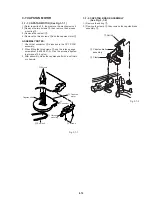
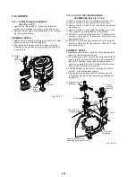
3-7-1. CAPSTAN MOTOR (See Fig.3-7-1)
1) Refer to section 3-2. then remove the mechanism unit.
2) Remove the two screws
2
, then remove the harness
mounting
1
.
3) Remove the reel belt
3
.
4) Remove the three screws
5
and the capstan motor
6
.
ASSEMBLY NOTES:
1. Check that connector
4
is inserted in the CP-1 PWB
assembly.
2. When fitting the thre screws
5
, use the torque gauge
screwdriver (J-6082-047-A). Give the screws a tighten-
ing torque of 3.5 kg/cm.
3. After assembly, clean the capstan shaft with a soft cloth
or chamois.
5
Screws
6
Capstan
motor
4
Connector
1
Harness
mounting
2
Screws
3
Reel belt
Capstan shaft
Fig. 3-7-1
3-7-2. CAPSTAN BRAKE ASSEMBLY
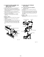
(See Fig. 3-7-2)
1) Remove the spring
1
.
2) Remove the clamp
2
, then remove the capstan brake
assembly
3
.
1
Spring
3
Capstan brake
assembly
2
Clamp
Fig. 3-7-2
Summary of Contents for SLV-L45AR
Page 6: ...1 2 ...
Page 7: ...1 3 ...
Page 8: ...1 4 ...
Page 9: ...1 5 ...
Page 10: ...1 6 ...
Page 11: ...1 7 ...
Page 12: ...1 8 E ...
Page 17: ...3 2 MECHANISM CONNECTION DIAGRAM ...
Page 18: ...3 3 3 4 SLV L45AR L65HFAR L75HFAR OVERALL WIRING DIAGRAM SLV L45AR ...
Page 19: ...SLV L45AR L65HFAR L75HFAR OVERALL WIRING DIAGRAM SLV L65HFAR L75HFAR 3 5 3 6 ...
Page 20: ...3 7 3 8 SLV L45AR L65HFAR L75HFAR SYSTEM CONTROL SERVO CIRCUIT DIAGRAM SLV L45AR ...
Page 21: ...3 9 3 10 SLV L45AR L65HFAR L75HFAR SYSTEM CONTROL SERVO CIRCUIT DIAGRAM SLV L65HFAR L75HFAR ...
Page 25: ...SLV L45AR L65HFAR L75HFAR 4 3 4 4 CP 1 BOARD VA A VIDEO AUDIO TUNER CIRCUIT DIAGRAM SLV L45AR ...
Page 33: ...4 19 4 20 CP 1 BOARD SY A SYSTEM CONTROL SERVO CIRCUIT DIAGRAM SLV L65HFAR L75HFAR ...

