S95E Sony
34
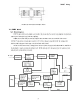
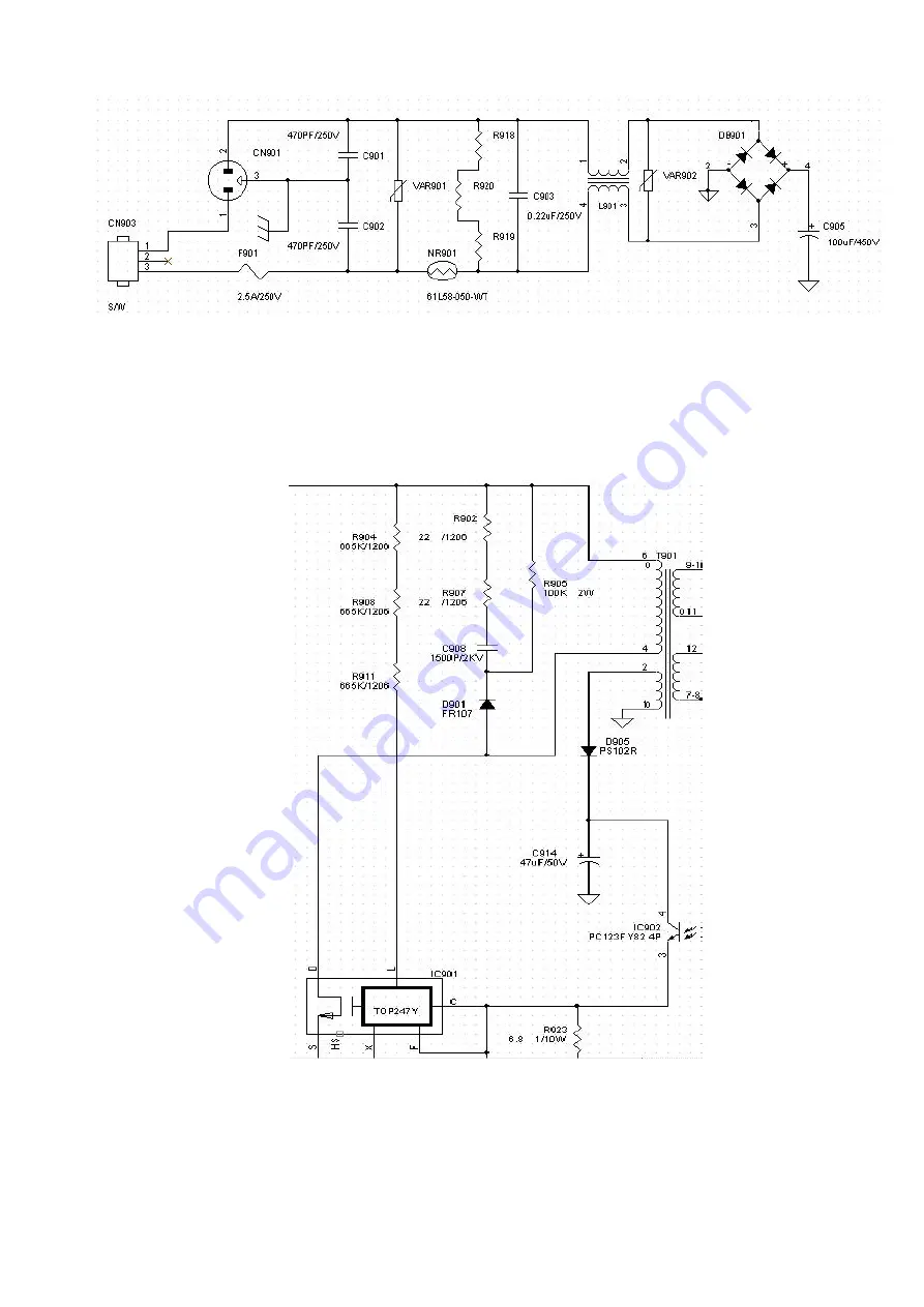
1.414 to AC after it is commuted by bridge rectifier (BD901) and filtered by the capacitance (C905).
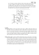
Start-up circuit:
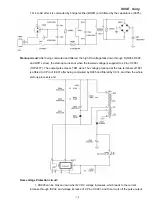
After being commuted and filtered, the high DC voltage falls down through R (R904, R908,
and R911 series), the start-up carries out when the lowered voltage is supplied to L Pin of IC901
(TOP247Y). The output pulse makes T901 work. The voltage produced at the two terminals of T901
is offered to C Pin of IC901 after being commuted by D905 and filtered by C914, and then the whole
start-up process is end.
Over-voltage Protection circuit:
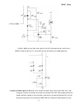
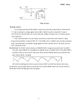
1. ZD903 can be broken down when12V DC voltage increases, which leads to the current
increase through IC902, and voltage increase of C Pin of IC901, and then it cuts off the pulse output.
Summary of Contents for S95E
Page 1: ...S95E Sony 1 Service Manual TFT LCD COLOR COMPUTER DISPLAY SONY ...
Page 3: ...S95E Sony 3 1 Precaution Warning on power connections Installation ...
Page 4: ...S95E Sony 4 Handing the LCD screen Maintenance Transportation ...
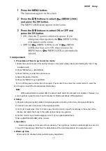
Page 10: ...S95E Sony 10 Adjustment steps of each menu ...
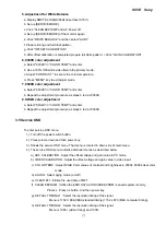
Page 11: ...S95E Sony 11 ...
Page 12: ...S95E Sony 12 ...
Page 13: ...S95E Sony 13 ...
Page 14: ...S95E Sony 14 ...
Page 15: ...S95E Sony 15 ...
Page 16: ...S95E Sony 16 ...
Page 17: ...S95E Sony 17 ...
Page 18: ...S95E Sony 18 ...
Page 19: ...S95E Sony 19 ...
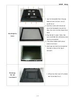
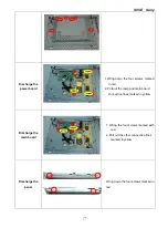
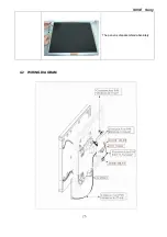
Page 26: ...S95E Sony 26 The panel is disassembled absolutely 4 2 WIRING DIAGRAM ...
Page 27: ...S95E Sony 27 4 3 Monitor Exploded View ...
Page 39: ...S95E Sony 39 ...
Page 63: ...S95E Sony 63 8 Schematic ...
Page 64: ...S95E Sony 64 ...
Page 65: ...S95E Sony 65 ...
Page 66: ...S95E Sony 66 ...
Page 67: ...S95E Sony 67 ...
Page 68: ...S95E Sony 68 ...
Page 69: ...S95E Sony 69 ...

