S95E Sony
33
BA9741F:
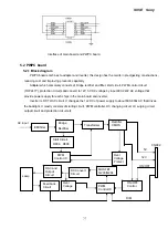
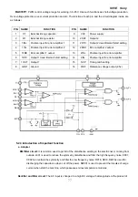
PWM control, voltage range for working: 3.6~35V, Has such functions as short-voltage protection,
Over-voltage protection, over-current protection and etc. The function of each pin and the circuit diagram inside are
as follows
:
PIN NAME
FUNCTION
PIN NAME
FUNCTION
1
CT
External timing capacitor
9
VCC
Power supply
2
RT
External timing resistor
10
2OUT
Output 2
3
1IN+
Positive input for error amplifier 1
11
2DTC
Output 2 dead time/soft start setting
4
1IN-
Positive input for error amplifier 2
12
2FBK
Error amplifier 2 output
5
1FBK Error amplifier 1 output
13
2IN+
Positive input for error amplifier
6
1DTC Output 1 dead time/soft start setting
14
2IN-
Positive input for error amplifier
7
1OUT Output 1
15
SCP
Timing latch setting
8
GND
Ground
16
REF
Reference voltage output (2.5v)
5.2.3 Introduction of important function
a. Adapter
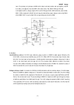
EMI filter circuit:
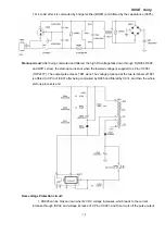
It is common used to get rid of the disturbance existing in the electric net or coming from
outside. L901 is used to reduce the symmetry disturbance and filter the high frequency noise; C901,
C902 can restrain the symmetry and filter the low frequency noise; R918, R919, R920 is used for
discharging the capacitance when cut off the power. NR901 is used to prevent the impulse of surge
current when start the machine, which possesses minus temperature modulus.
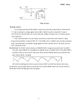
Rectifier and filter circuit:
The AC input is changed to a high DC voltage, that magnitude is the product of
Summary of Contents for S95E
Page 1: ...S95E Sony 1 Service Manual TFT LCD COLOR COMPUTER DISPLAY SONY ...
Page 3: ...S95E Sony 3 1 Precaution Warning on power connections Installation ...
Page 4: ...S95E Sony 4 Handing the LCD screen Maintenance Transportation ...
Page 10: ...S95E Sony 10 Adjustment steps of each menu ...
Page 11: ...S95E Sony 11 ...
Page 12: ...S95E Sony 12 ...
Page 13: ...S95E Sony 13 ...
Page 14: ...S95E Sony 14 ...
Page 15: ...S95E Sony 15 ...
Page 16: ...S95E Sony 16 ...
Page 17: ...S95E Sony 17 ...
Page 18: ...S95E Sony 18 ...
Page 19: ...S95E Sony 19 ...
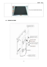
Page 26: ...S95E Sony 26 The panel is disassembled absolutely 4 2 WIRING DIAGRAM ...
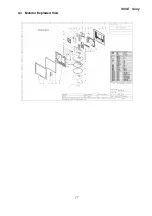
Page 27: ...S95E Sony 27 4 3 Monitor Exploded View ...
Page 39: ...S95E Sony 39 ...
Page 63: ...S95E Sony 63 8 Schematic ...
Page 64: ...S95E Sony 64 ...
Page 65: ...S95E Sony 65 ...
Page 66: ...S95E Sony 66 ...
Page 67: ...S95E Sony 67 ...
Page 68: ...S95E Sony 68 ...
Page 69: ...S95E Sony 69 ...

