6
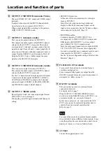
• PROJECTOR position
In this case, the same output signal is coming as
same as OUTPUT 1.
Select this side when connecting a multi-scan
display to which 15k component signals can be
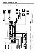
input, such as a projector. See the "System configu-
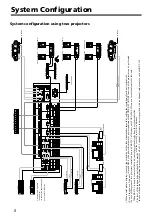
ration using two projectors" (Page 8).
• MONITOR position
Composite signals of VIDEO INPUT 1 to 6
are output only to VIDEO OUTPUT terminal, and
RGB signals of RGB INPUT 7 to 10 are output
only to RGB/Y R-Y B-Y output terminal.
Since the component signals are not output to RGB/
Y R-Y B-Y OUTPUT terminal, this is appropriate
for such a system that uses a computer monitor and a
video monitor for OUTPUT 2, respectively.
See the "System configuration using a Projector and
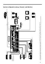
Monitors" (Page 9).
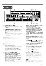
!º
PARALLEL I/O terminals
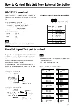
Crosspoint of this unit can be switched from an
external control panel, etc.
Since crosspoint tally signals are output from the
OUTPUT terminal, this can be used for indication of
crosspoint, etc. Refer to page 11.
!¡
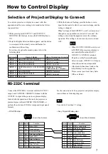
RS-232C terminals
This can control a projector or plasma display
connected to this unit.
For details, refer to page 7.
When OUTPUT 2 CONTROL/REMOTE select
switch is set to the REMOTE side in OUTPUT 2, an
external controller, etc. can control this unit.
In this case, a projector, etc. connected to the OUT-
PUT 2 side can not be controlled from this unit, so
control it from the external controller side.
Refer to page 11.
For some of the projector or plasma display models,
when switched between different video signals, it may
occur that picture become deteriorate or need time to
display etc, however, it is not a failure of unit.
!™
AC Inlet
Connect the supplied power cord.
Location and function of parts
6
OUTPUT 2/MONITOR terminals (Video)
These are RGB/Y R-Y B-Y output and VIDEO output
terminals.
It outputs video signal of the INPUT channel which
was selected at the crosspoint of OUTPUT 2.
When output signals differ according to the position
of
9
OUTPUT 2 MODE switch.
7
OUTPUT 1 terminals (Audio)
This is an audio output terminal of OUTPUT 1.
This outputs the audio signals of the INPUT channel
selected by the OUTPUT 1 crosspoint. This output
corresponds to 5.1 channel surround output, when the
signals are input from ch5 and 6. Audio signal of L/R
stereo input of channels other than channels 5 and 6 is
output from the FRONT L and R terminals. The L/R
Outputs (XLR-3-32 type, +4dBu) output the same
signals as the FRONT L/R terminals.
8
OUTPUT 2/MONITOR terminals (Audio)
This is an stereo output terminal of OUTPUT 2.
This outputs the audio signals of the INPUT channel
selected by the OUTPUT 2 crosspoint.
For the 5.1 channel surround input signals of channels
5 and 6, mixed audio signal of FRONT L, REAR L,
CENTER and WOOFER is output to the L channel,
and mixed signal of FRONT R, REAR R, CENTER,
and WOOFER is output to the R channel.
9
OUTPUT 2 MODE switch
By setting this switch, the video output signal format
of OUTPUT 2 can be changed.
Turning the power ON again validates this change of
setting.
Note


