14
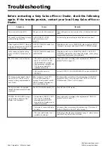
Power cannot be turned ON.
The sound level difference is large
when switching channels.
Video signals of INPUT 1 through
6 do not output from the OUTPUT
2 RGB/Y R-Y B-Y terminal.
In the connected display setting
mode, OUTPUT 2 button does no
flash.
RS-232C cannot control this unit.
The color of video signals output
from OUTPUT 1 and 2 are not
normal, or the synchronization is
out of order.
The system cannot be operated
though the front crosspoint button
is pressed.
POWER ON/STANDBY or input
signal formats selection of the
display is not available.
Troubleshooting
Symptom
Couses
Remedy
The power cord is disconnected.
AUDIO INPUT LEVEL
select switch is not set
properly.
OUTPUT 2 MODE switch is set
to MONITOR.
OUTPUT 2 MODE switch is set
to MONITOR.
• The cable is not connected to
RS-232C OUTPUT 2 CON-
TROL/REMOTE terminal.
• Each parameter setting for RS-
232C dose not match the
condition of this unit.
• The switch is not set to
REMOTE.
BNC terminals of each OUT-
PUT, and the connection
between D-sub terminal and the
INPUT terminal of display are
not connected properly.
The LOCK switch is turned ON.
• Connection of RS-232C OUT-
PUT 1 and 2 CONTROL
terminals and the RS-232C
terminal of the display are not
connected properly.
• Selection of connected display
is wrong.
• The connected display is not
available for this unit.
Connect the power cable securely in the AC Inlet and the wall
outlet.
Set the level again according to that of the unit to connect.
When this switch is set to MONITOR, video signals of INPUT
1 through 6 are output only from OUTPUT 2 VIDEO terminal.
When this switch is set to MONITOR, RS-232C OUTPUT 2
CONTROL terminal does not control the display, so the setting
of applicable display cannot be performed.
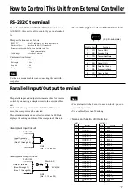
Connect the cable according to the explanation of "RS-232C
terminal" (refer to page 11).
Set the OUTPUT 2 CONTROL/REMOTE switch to REMOTE.
Re-connect them according to the explanation of "OUTPUT 1
terminals (Video)" (refer to page 5) and "OUTPUT 2/MONI-
TOR terminals (Video)" (refer to page 6).
Turn OFF the LOCK switch.
Connect the cable according to the explanation of "RS-232C
terminal" (refer to page 7).
Re-connect them according to the explanation of "Selection of
Projector/Display to Connect" (refer to page 7).
For displays other than the explanation in page 7, please contact
your local Sony Sales Office or Dealer.
http://www.world sony.com/
Printed on recycled paper
Sony Corporation
Printed in Japan
Before contacting a Sony Sales office or Dealer, check the following
again. If the trouble persists, contact your local Sony Sales office or
Dealer.


