1
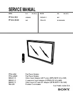
PFM-42B2/42B2E
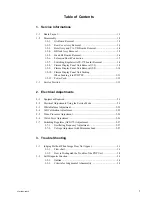
Table of Contents
1. Service Informations
1-1.
Board Layout ............................................................................................... 1-1
1-2.
Disassembly ................................................................................................ 1-2
1-2-1.
QA Board Removal .................................................................... 1-2
1-2-2.
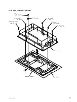
Rear Cover Assy Removal ......................................................... 1-3
1-2-3.
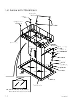
Bezel Assy and YA, YB Boards Removal ................................. 1-4
1-2-4.
B Block Assy Removal .............................................................. 1-5
1-2-5.
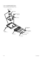
B and B1 Boards Removal ......................................................... 1-6
1-2-6.
Extension Board Connection ...................................................... 1-7
1-2-7.
Switching Regulator (APS-179 board) Removal ....................... 1-8
1-2-8.
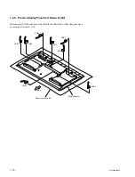
Plasma Display Panel Unit Removal (1/2) ................................. 1-9
1-2-9.
Plasma Display Panel Unit Removal (2/2) ............................... 1-10
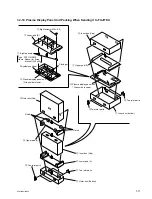
1-2-10. Plasma Display Panel Unit Packing
When Sending it to FUJITSU .................................................. 1-11
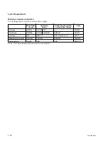
1-2-11. Power Cord ............................................................................... 1-12
1-3.
Service Position ......................................................................................... 1-13
2. Electrical Adjustments
2-1.
Equipment Required .................................................................................... 2-1
2-2.
Electrical Adjustments Using the Service Mode ........................................ 2-1
2-3.
White Balance Adjustment ....................................................................... 2-25
2-4.
A/D Calibration Adjustment ..................................................................... 2-25
2-5.
Video Processor Adjustment ..................................................................... 2-26
2-6.
Watch Error Adjustment ........................................................................... 2-26
2-7.
Switching Regulator (APS-179) Adjustment ............................................ 2-27
2-7-1.
Oscillating Frequency Adjustment ........................................... 2-27
2-7-2.
Voltage Adjustment with Minimum Load ............................... 2-27
3. Trouble Shooting
3-1.
Judging Method When Image Does Not Appear ........................................ 3-1
3-1-1.
Flow chart ................................................................................... 3-1
3-1-2.
How to Distinguish the Trouble of the PDP Unit. ..................... 3-2
3-2.
Self Diagnosis Function .............................................................................. 3-3
3-2-1.
Outline ........................................................................................ 3-3
3-2-2.
Criteria for Judgment of Abnormality ........................................ 3-3
Summary of Contents for PFM-42B2
Page 8: ......
Page 22: ......
Page 102: ......
Page 136: ......
Page 138: ...Sony Corporation B P Company 9 870 315 01 English 02GS16 1 Printed in Japan 2002 7 ...

