


1-9
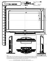
PFM-42B2/42B2E
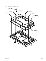
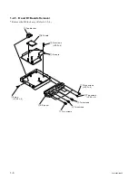
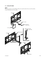
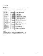
1-2-8. Plasma Display Panel Unit Removal (1/2)
* Remove the Bezel assy. (Refer to 1-2-3.)
* Remove the B block assy. (Refer to 1-2-4.)
* Remove the switching regulator. (Refer to 1-2-7.)
Remove those parts according to
numbers
1
through
@/
.
0
Screw (
+
PSW4
x
8)
9
Two screws (
+
PSW5
x
40)
4
Two screws (
+
PSW5
x
40)
5
Screw (
+
PSW4
x
8)
!\
Screw (
+
PSW3
x
16)
!,
Three screws
(
+
PSW4
x
16)
!.
Three S boards
@/
Three S board brackets
Wire (for reference)
!;
S board
!'
S board bracket
!-
Corner bracket (B)
6
Corner bracket (A)
7
Two screws
(
+
BVTP4
x
16)
!=
Two screws
(
+
PSW5
x
40)
![
Screw
(
+
PSW4
x
8)
2
Screw
(
+
PSW4
x
8)
1
Two screws
(
+
PSW5
x
40)
8
Inlet bracket
!]
Corner bracket (A)
3
Corner bracket (B)
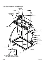
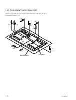
Note) If two wires attached on the glass surface of
plasma display panel, be careful not to cut them.
@-
Shield sheet
Main chassis
Top side
Conductive cushion
Summary of Contents for PFM-42B2
Page 8: ......
Page 22: ......
Page 102: ......
Page 136: ......
Page 138: ...Sony Corporation B P Company 9 870 315 01 English 02GS16 1 Printed in Japan 2002 7 ...