2-10
PFM-42B2/42B2E
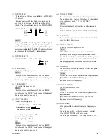
(12)CP PLACEMENT
Clamp pulse position is set.
The clamp pulse position is set starting from the
trailing edge of horizontal sync signal (when data is
000). Increasing this value moves the clamp pulse in
the direction toward the picture area.
The clamp pulse generating position “Tcp” is given by
the following equation starting from the trailing edge
of horizontal sync signal.
Tcp = CP PLACEMENT / [horizontal sync frequency
x
TOTAL H PIXEL] (in seconds)
(13)CP DURATION
Clamp pulse width is set.
The clamp pulse width is set starting from the position
that is determined by CP PLACEMENT. Increasing
this value widens the clamp pulse width in the direc-
tion toward the picture area.
The clamp pulse width “Wcp” is given by the follow-
ing.
Wcp = CP DURATION / [horizontal sync frequency
x
TOTAL H PIXEL] (in seconds)
(14)INTERLACE MODE
Whether the input signal is interlaced or not is set.
ON : When the input signal is the interlaced signal.
OFF : When the input signal is not the interlaced
signal.
(15)FIELD MODE
Whether the interlaced signal is processed within a
field or within a frame, is set.
ON : When the input interlaced signal is processed
within a field.
OFF : When the interlaced signal is processed within
a frame.
Select the ON position when a signal has a low co-
relationship between the two fields within a frame
such as moving picture.
(16)FRAMELOCK MODE
Whether the PDP display picture is synchronized with
the input signal to scan converter or not, is set.
ON : The PDP display picture is synchronized with
the input signal.
OFF : The PDP display picture is asynchronous with
the input signal.
When moving picture (animation) is going be dis-
played, select the ON position.
n
This item can be set to ON as long as the vertical frequency
of the input signal is in the range of 50 to 60 Hz.
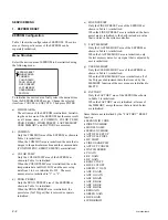
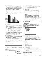
(17)MATRIX SELECT
The color difference matrix when the YUV signal is
being input, is set.
(18)PICTURE AGC
Whether the PICTURE AGC is turned ON or OFF is
set.
Result of this setting becomes the initial value of the
user menu PICTURE AGC.
This function becomes valid only when the COMPOS-
ITE/YC/YUV signal is being received.
(19)ASPECT
The desired aspect ratio is selected from the aspect
ratios of 4
x
3 or 16
x
9 or W ZOOM or LB ZOOM.
Result of this setting becomes the initial value of the
user menu ASPECT.
n
The W ZOOM, can not be selected when the ZOOM is
in the range of x 2 to x 4.
(20)ZOOM
The desired zoom ratio is selected from the zoom
ratios of
x
1 or
x
2 or
x
3 or
x
4. Result of this
setting becomes the initial value of the user menu
ZOOM.
n
Any zoom ratios other than x 1 cannot be selected
when the ASPECT is W ZOOM, LB ZOOM.
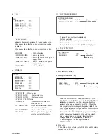
(21)APERTURE INIT
The desired aperture is selected from HIGH or MID or
LOW. Result of this setting becomes the initial value
of the user menu APERTURE.
(22)APERTURE HIGH
The scaling filter value when selecting HIGH of the
APERTURE, is set. The scaling filter value can be set
in the range of 000 to 011. (Refer to the Supplement
to APERTURE in the following paragraph.)
(23)APERTURE MID
The scaling filter value when selecting MID of the
APERTURE, is set. The scaling filter value can be set
in the range of 000 to 011. (Refer to the Supplement
to APERTURE in the following paragraph.)
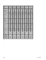
MATRIX SELECT : ITU601
MATRIX SELECT : ITU709
Summary of Contents for PFM-42B2
Page 8: ......
Page 22: ......
Page 102: ......
Page 136: ......
Page 138: ...Sony Corporation B P Company 9 870 315 01 English 02GS16 1 Printed in Japan 2002 7 ...

