2-27
PFM-42B2/42B2E
2-7. Switching Regulator (APS-179) Adjustment
Preparation : Remove the switching regulator from the main unit.
2-7-1. Oscillating Frequency Adjustment
1.
Short-circuit pins-3 and -4 of PH101, PH-107, PH-111 and PH-902 respectively.
2.
Short-circuit gate and source of Q302 and Q308.
3.
Apply DC 22 V to C122 and adjust the oscillating frequency as listed below.
Between gate and source
ADJ
Specification
Q108
RV101
83k
±
0.5 kHz
Q113
RV102
84k
±
0.5 kHz
Q154
RV150
73k
±
0.5 kHz
Q504
RV901
67k
±
0.5 kHz
Q704
RV950
65k
±
0.5 kHz
2-7-2. Voltage Adjustment with Minimum Load
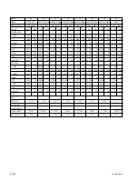
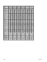
Load of each output
Output
Pin No.
Minimum load Maximum load
Vcc (5 V)
CN23
3
pin
2.0A
6.0A
Vs
CN23
8
pin
0.5A
4.0A
Va
CN23
1
pin
0.1A
3.5A
St-by 5 V
CN9002
1
pin
0.1A
0.3A
Vpr2
CN6
1
0A
0.05A
26 V
CN9003
1
pin
0.1A
1.0A
A13.5 V
CN9001
7
pin
0.1A
2.0A
D3.3 V
CN9002
6
pin
0A
1.5A
D5 V
CN9002
!/
pin
0A
1.8A
A6 V
CN9001
3
pin
0A
1.5A
Audio
+
12 V
CN9004
8
pin
0A
0.71A
Audio
_
12 V
CN9004
5
pin
0A
0.71A
Summary of Contents for PFM-42B2
Page 8: ......
Page 22: ......
Page 102: ......
Page 136: ......
Page 138: ...Sony Corporation B P Company 9 870 315 01 English 02GS16 1 Printed in Japan 2002 7 ...

