Sony NXL-IP55 Operation Manual Download Page 21

Menus

21

Menus

Menu Structure

The settings for this unit are configured via the web menu.

The web menu contains the following pages.

After configuring settings in each page, click the [Apply] button to apply the settings. If you switch to a different page or 

close the web browser without clicking the [Apply] button, the settings will not be applied.

To view the most recent status, perform a force reload on the web browser. If a force reload is not performed, old 

information may be displayed.

Menu legend

• Underlined values indicate the default settings.
• The “Target” column indicates whether the setting can be imported and exported.
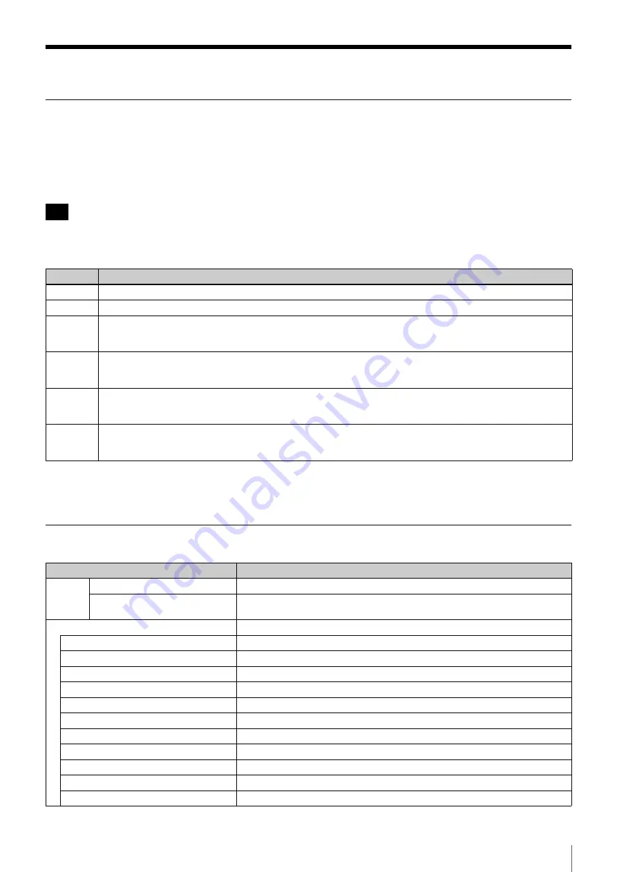
[Status] Page

Note

Page

Description

Status

Displays the status of the unit.

Operator

Allows you to operate the unit.

I/O

Allows you to configure the I/O of the unit. As this unit may not function properly depending on settings, do not 
open this page during operations.
Password entry is required to open this page.

Structure

Allows you to configure the relationship between this unit and the other NXL-IP55 unit (i.e., connection 
destination). As this unit may not function properly depending on settings, do not open this page during operations.
Password entry is required to open this page.

Network

Allows you to configure the network accessed by the unit. As this unit may not function properly depending on 
settings, do not open this page during operations.
Password entry is required to open this page.

Others

Allows you to configure other settings for the unit. As this unit may not function properly depending on settings, do 
not open this page during operations.
Password entry is required to open this page.

Item

Description

Refresh

Click this to update the displayed information.

Automatic Updating

Automatically updates the display periodically. This is disabled under default 
settings.

Table of Contents and Diagnosis

Displays a table of contents for items and status information.

1. GenLock

Displays the GenLock status. Click this to jump to a detailed display.

2. Video Input

Displays the video input status. Click this to jump to a detailed display.

3. Audio Input

Displays the audio input status. Click this to jump to a detailed display.

4. System Status

Displays the system configuration status. Click this to jump to a detailed display.

5. Stream

Click this to jump to a status display for the transmitted content.

6. Video Out Source

Click this to jump to a status display for the video output.

7. Analog Audio out

Click this to jump to a status display for the analog audio configurations.

8. Network Configuration

Click this to jump to a status display for the network configurations.

9. Network Conditions

Displays the network status. Click this to jump to a detailed display.

10. Device Status

Displays self-diagnosis results. Click this to jump to a detailed display.

11. Device Information

Click this to jump to a device information display.

Summary of Contents for NXL-IP55

Page 1: ...IP LIVE PRODUCTION UNIT NXL IP55 OPERATION MANUAL English 1st Edition Revised 1 ...

Page 2: ...l Usage Example 8 GPIO Signal Usage Example 8 Names and Functions of Parts 9 Front 9 Rear 9 Settings 11 Configuring Settings 11 Input Output Phases for HD SDI Signals 15 Settings Examples 17 Operation 20 Starting Video Transmission 20 Outputting Color Bars and Tone Signal 20 Displaying the Status 20 Menus 21 Menu Structure 21 Status Page 21 Operator Page 24 I O Page 25 Structure Page 29 Network Pa...

Page 3: ... of two channels 48 kHz 24 bit are available for audio signals analog audio signals and intercom signals embedded on HD SDI signals up to eight channels in the same direction HD SDI embedded audio can be transmitted on Ch1 to Ch2 or Ch1 to Ch4 The audio will not be transmitted on Ch5 and above Metadata attached to HD SDI signals cannot be transmitted When transferring Dual Link SDI audio signals c...

Page 4: ...era 1 Return signal HD SDI Main line signals 1 to 3 HD SDI NXL IP55 Network Video router Camera 2 Camera 3 Main line signal 1 HD SDI Tally signal Synchronization signal Return signal HD SDI Main line signal 2 HD SDI Tally signal Synchronization signal Return signal HD SDI Main line signal 3 HD SDI Tally signal Synchronization signal NXL IP55 Synchronization signal Tally signal Return signal HD SDI...

Page 5: ...eturn signals Camera 1 Return signals 1 and 2 HD SDI Main line signals 1 and 2 HD SDI NXL IP55 Network Video router Camera 2 Main line signal 1 HD SDI Tally signal Synchronization signal Return signals 1 and 2 HD SDI Main line signal 2 HD SDI Tally signal Synchronization signal NXL IP55 Synchronization signal Tally signal Return signals 1 and 2 HD SDI ...

Page 6: ...nsmitted Three channels are available for transmitting return signals Camera 1 Return signals 1 to 3 HD SDI Main line signal HD SDI NXL IP55 Network Video router Main line signal 1 HD SDI Tally signal Synchronization signal NXL IP55 Synchronization signal Tally signal Return signals 1 to 3 HD SDI ...

Page 7: ...re at line level an external microphone amplifier is necessary when using a microphone Switcher Microphone Camera 1 Main line signals 1 to 3 HD SDI 1 NXL IP55 Network Camera 2 Camera 3 Main line signal 1 HD SDI Tally signal Synchronization signal Main line signal 2 HD SDI Tally signal Synchronization signal Main line signal 3 HD SDI Tally signal Synchronization signal NXL IP55 Synchronization sign...

Page 8: ...lable for transmitting tally signals via the unit s TALLY GPIO connector GPIO Signal Usage Example Two groups of four GPIO General Purpose Input Output signals can be transmitted via the unit s TALLY GPIO connector The transmission direction can be changed for each group Intercom system Intercom system PROD ENG PROD ENG Camera control unit Camera NXL IP55 NXL IP55 Network NXL IP55 Network NXL IP55...

Page 9: ...Lit blue Connection has been established and the unit is waiting for signal output to stabilize Video signals are not output during this time Off Not connected to the LAN cALARM indicator Lights red when an error is detected Check the Status page of the web menu for details on the error The indicator blinking red indicates an internal error If restarting the unit does not resolve the problem consu...

Page 10: ...r that supports 1000BASE T Video signals and control signals are transmitted between multiple units of this device via a gigabit network This single connector has two IP addresses Always connect to a 1000BASE T network The unit will not operate with other network types Connect the unit using a CAT5e LAN cable or above gCONTROL connector This is a network connector that supports 100BASE TX Connect ...

Page 11: ...two IP addresses Main 1 and Main 2 When you configure the IP address for Main 1 a sequential IP address is configured for Main 2 automatically Make sure that the IP addresses do not overlap with other devices Host IP Address 1 2 Enter the IP address for Main 1 Host IP Address 2 2 This is configured automatically when you enter an address for Host IP Address 1 2 This cannot be modified Subnet Mask ...

Page 12: ...nsmit 1Receive for the cameras and 1Transmit 3Receive for the video router Alternatively if 3Transmit 1Receive is specified specify 1Transmit 3Receive for the partner device If 2Transmit 2Receive is specified specify 2Transmit 2Receive again for the partner device If 1080 59 94P Dual Link or 1080 50P Dual Link is selected in Video Format Structure is fixed to 2Transmit 2Receive and Dual Link 1 ope...

Page 13: ...r for the tally signal transmitter and Receiver for the receiver The transmission method cannot be changed on an individual basis Next specify the interface for the input tally signal under Tally Input on the I O page Tally Input Select Contact or Power TTL Output is fixed at Contact 10 GPIO settings The transmission direction of the GPIO signal is specified under Signal Direction on the Structure...

Page 14: ...ear the Test mode checkboxes for both the local and partner units Test items and results display The following items are checked and the results will be displayed as Pass Failed or Borderline Notes Item Description Physical link Test results for the MAIN connector s physical interface Pass 1000BASE T connection established properly Failed 1000BASE T connection is not established properly or cable ...

Page 15: ...ings for condition 4 Set Reference out V Phase on the I O page to 0 Set Frame Synchronizer on the Structure page to OFF Settings for condition 5 Adjust input equipment and configure the phases so that they meet condition 4 Alternatively adjust the phase of the input equipment using Reference out V Phase on the I O page and meet condition 4 Set Frame Synchronizer on the Structure page to OFF Settin...

Page 16: ...izer Note Main line signal HD SDI IN Return signal HD SDI OUT REF OUT HD SDI OUT Main line signal HD SDI IN Return signal REF IN Transmitter Receiver Phase is identical when Reference out V Phase is 0 Delayed Phase is identical when Reference in V Phase is 0 ...

Page 17: ...e Follower Video router Receiver 1Transmit 3Receive Leader Main Video Direction Structure Network GenLock Camera Transmitter 2Transmit 2Receive Follower Video router Receiver 2Transmit 2Receive Leader Synchronization signal cameras 1 to 3 Camera side Main line signal cameras 1 to 3 Return signal cameras 1 to 3 Monitor Synchronization signal Main line signal cameras 1 to 3 Return signal Monitor Rou...

Page 18: ...nal The following table indicates configuration examples for the web menu Main Video Direction Structure Network GenLock Camera Transmitter 1Transmit 3Receive Follower Video router Receiver 3Transmit 1Receive Leader Main Video Direction Structure Network GenLock Frame Synchronizer Camera Transmitter 3Transmit 1Receive Follower SDI in 1 Video router Receiver 1Transmit 3Receive Leader OFF Synchroniz...

Page 19: ...Main Video Direction Structure Network GenLock Frame Synchronizer Camera Transmitter 3Transmit 1Receive Leader OFF Video router Receiver 1Transmit 3Receive Follower ALL Synchronization signal on camera side Synchronization signal on video router side The frame synchronizer on the video router side is applied to all HD SDI inputs outputs Camera side Video router side The synchronization signals on ...

Page 20: ...and the partner unit corresponding to the selected input signal To switch the output connector signals to color bars place a check mark in SDI out 1 to SDI out 4 or Monitor out Color Bars Select Select the type of color bars you want to output Tone Level Set the level of the tone signal added to the color bars The setting is in dBFS units Select to disable the tone signal When finished changing se...

Page 21: ...ettings do not open this page during operations Password entry is required to open this page Others Allows you to configure other settings for the unit As this unit may not function properly depending on settings do not open this page during operations Password entry is required to open this page Item Description Refresh Click this to update the displayed information Automatic Updating Automatical...

Page 22: ...ormat of the video signal Signal Direction Tally Displays the transmission direction of the tally signal GPIO Group 1 Displays the transmission direction of the GPIO Group 1 signal GPIO Group 2 Displays the transmission direction of the GPIO Group 2 signal Structure Settings During the connection process OK appears here when the settings on the partner unit s Structure page are correct and Error a...

Page 23: ...Devices IP Address 1 Displays the IP addresses of computers connected to the MAIN connector network IP Address 2 IP Address 3 IP Address 4 IP Address 5 IP Address 6 IP Address 7 IP Address 8 Control Port IP Address Displays the IP address and MAC address of the CONTROL network Subnet Mask Displays the subnet mask of the CONTROL network Default Gateway Displays the default gateway of the CONTROL ne...

Page 24: ...sh Click this to update the displayed information Item Description Target Apply Click this after modifying the settings to apply them 1 Connection Auto Connection Specifies whether to automatically connect the unit at startup This is enabled under default settings Y Connect When Auto Connection is disabled this starts connection manually N 2 Monitor out Character Display Specifies whether to embed...

Page 25: ...ult settings Y Tone Level Sets the audio level of the tone signal added to the color bars 0 16 18 20 22 24 dBFS Y 4 Operation Manual Language Select Selects the language of the operation manual N View Operation Manual PDF Click this to display the operation manual in the selected language N 5 License Information View License Information Displays detailed license information and a list of software ...

Page 26: ...Specifies the vertical phase of this unit for the output synchronization signal 562 to 0 to 562 for 1080 59 94i 50i 375 to 0 to 375 for 720 59 94P 50P Y 4 Embedded Audio Enable SDI out 1 Embeds audio on HD SDI OUT connector 1 This is enabled under default settings Y SDI out 2 Embeds audio on HD SDI OUT connector 2 This is enabled under default settings Y SDI out 3 Embeds audio on HD SDI OUT connec...

Page 27: ...put from Analog 5 and 6 of the AUDIO INTERCOM connector Y SDI in 2 When Analog Audio Direction is set to Input this selects the audio signals that are transmitted with SDI in 2 Embedded Audio signal embedded on the SDI signal Analog in 1 2 Audio signal input from Analog 1 and 2 of the AUDIO INTERCOM connector Analog in 3 4 Audio signal input from Analog 3 and 4 of the AUDIO INTERCOM connector Anal...

Page 28: ...IN connector 1 Opposite SDI in 2 Outputs the signal that corresponds to the input of the partner unit s HD SDI IN connector 2 Opposite SDI in 3 Outputs the signal that corresponds to the input of the partner unit s HD SDI IN connector 3 Does not output audio Y Ch1 2 Ch3 4 Selects whether to output Ch 1 and 2 or Ch 3 and 4 Y Analog out 5 6 When Analog Audio Direction is set to Output this selects t...

Page 29: ...i 1080 50i 720 59 94P 720 50P 1080 29 97PsF 1080 25PsF 1080 59 94P Dual Link 1080 50P Dual Link Y 4 Video Codec Rate Stream 1 a Selects the video transmission rate of the corresponding stream Selecting High enables high resolution images but requires a large transmission band High Transmits high resolution video This requires a large transmission band Low Transmits low resolution video Y Stream 2 ...

Page 30: ... Transmits the Ch 1 and 2 audio signals of the corresponding stream This is enabled under default settings Y ch3 4 Transmits the Ch 3 and 4 audio signals of the corresponding stream The ch 3 4 checkbox cannot be selected by itself This is disabled under default settings Y Delay When using a frame synchronizer use this to increase the delay in the audio signal The default setting is 0 Y Stream 4 a ...

Page 31: ...red automatically based on the first address The default setting is 192 168 10 2 N Subnet Mask Specifies the MAIN connector s subnet mask The default setting is 255 255 255 0 N Destination IP Address 1 2 Specifies the first IP address of the partner unit s MAIN connector The default setting is 192 168 10 10 Y Destination IP Address 2 2 Displays the second IP address of the partner unit s MAIN conn...

Page 32: ...wer side N Packet loss Number of received video packet errors and number of packets lost during the test and the total number since the unit was turned on N Throughput informative Bit rate of the video packets received during the test reference value and the total byte count of the received packets N Apply Click this after modifying the settings to apply them Item Description Target Apply Click th...

Page 33: ...x to include stream mode and multicast settings when importing N Enable Device Name Place a check mark in the checkbox to include the device name setting when importing N Import Starts importing the configuration file N 5 Export System Configuration Saves the configuration file to a computer Export Starts exporting the configuration file Click Export to display a save file dialog and specify a fil...

Page 34: ...b connector 1 TALLY GPIO 25 pin D sub connector 1 MAIN RJ 45 1 1000BASE T CONTROL RJ 45 1 100BASE TX Supplied accessories AC adapter 1 Warranty 1 Operation guide 1 Clamp 1 Optional accessories Power cord Service Parts No 1 757 562 11 USA Canada 1 575 131 82 EU Dimensions Units mm inches To stabilize the unit use the screw holes two holes indicated in the above dimensions M3 at the bottom of the un...

Page 35: ...t 6 X 7 Analog Audio G 8 Intercom ENG Input X 9 Intercom PROD Input X 10 Intercom ENG Output X 11 Intercom PROD Output X 12 NC 13 GND 14 a Analog Audio in out 1 Y 15 a Analog Audio in out 2 Y 16 a Analog Audio in out 3 Y 17 a Analog Audio in out 4 Y 18 a Analog Audio in out 5 Y 19 a Analog Audio in out 6 Y 20 GND 21 Intercom ENG Input Y 22 Intercom PROD Input Y 23 Intercom ENG Output Y 24 Intercom...

Page 36: ...Public License LGPL applies Users of this product have the rights to acquire modify and or redistribute the source codes of the software pursuant to the terms and conditions of the GPL LGPL For detailed license information and a software package list see Operator page License Information of the web menu For details on acquiring source codes consult your Sony service representative ...

Page 37: ... for use by the purchasers of the equipment described in this manual Sony Corporation expressly prohibits the duplication of any portion of this manual or the use thereof for any purpose other than the operation or maintenance of the equipment described in this manual without the express written permission of Sony Corporation ...

Page 38: ...Sony Corporation NXL IP55 SY CN 4 450 805 02 1 2013 ...

Reviews: