background image

MEX-N5100BE/N5100BT/N5150BT

MEX-N5100BE/N5100BT/N5150BT

30

30

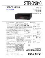
5-3.  BLOCK  DIAGRAM - PANEL/POWER SUPPLY Section -

REGULATOR

IC803

13

43

VOUT3

VIN0

9

SYNC

23

GA

TE1

44

GA

TE5

2

EN

3

LD4EN

4

ECO

6

ERR2

CN301 (2/2)

26

VIN2

41

VINSW

38

HSW1

VCC

15

9

AMP_REM

33 VOUT0
36 SW2

13

ACC

SYSTEM CONTROLLER

IC503 (3/3)

J801

(REMOTE IN)

84 RC_IN1

132 RE_IN1
131 RE_IN0
122 RE_ON

135 DOOR_SW

136 SIRCS

83 KEY_IN1
82 KEY_IN0

81 RC_IN0

40 LCD_DO

115 REMOTE1K

35 LCD_CLK
38 LCD_CE

76

RES

108

USB_OVR

49 KEY_ACK1

KEY BOARD (3/3)

LCD_DATA

LCD_CLK

LCD_CE

SIRC

KEY_1
KEY_0

RE_1
RE_0

PANEL_SW

15

VIN3

16

VIN4

RESET SIGNAL

GENERATOR

IC501

+1.5V

REGULATOR

IC703

+1.2V

REGULATOR

IC805

BU_1.5V

+3.3V

REGULATOR

IC1001

BT_3.3V

+3.3V

REGULATOR

IC002

TU_3.3V

FP_B+

DR_6V

DR_3.3V

BU_3.3V

TU_5V

20 VOUT4

118

USB_ON

112

BT_PWR

106

PWR_ECO

4

SERVO_ON

42

SYNC_OUT

104

EN_SYS

28 VOUT2

USB_VBUS

P

-COM_1.2V

AU_8.5V

ACC_IN 45

BU_IN 56

VBUSIN0 152

VCC

D818

D817

BATTERY

CHECK

Q813

ACCESSORY

CHECK

Q806

BACK UP

VOLTAGE DETECT

Q812, 814

REGULATOR

Q805

REGULATOR

Q804

D502

B+ SWITCH

Q803

POWER

CONTROL
Q801, 802

D802

D816

+6V

REGULATOR

IC804

+3.3V

REGULATOR

IC702

DR_1.5V

+1.5V

REGULATOR

IC704

7

SDA

8

SCL

I2C0_SCL

I2C0_SDA

I2C0_SDA,

I2C0_SCL

RESET

11

ILL

ILL_IN 79

MUTING

>006B

>005B

>001B

DIMMER
DETECT

Q807

D814

D1319

S001

RESET

BUFFER

Q1308

BUFFER

Q1307

(Page 28)

(Page 28)

(Page 29)

Summary of Contents for MEX-N5100BE

Page 1: ... ratio 73 dB Separation 50 dB at 1 kHz Frequency response 20 15 000 Hz MW LW Tuning range MW 531 1 602 kHz LW 153 279 kHz Antenna aerial terminal External antenna aerial connector Sensitivity MW 26 μV LW 50 μV FM1 FM2 87 5 108 0 MHz at 50 kHz step FM3 65 74 MHz at 30kHz step Antenna aerial terminal Tuning range External antenna aerial connector Intermediate frequency Usable sensitivity 8 dBf Selec...

Page 2: ...ircuit board within 3 times Be careful not to apply force on the conductor when soldering or unsoldering CD Player section Signal to noise ratio 120 dB Frequency response 10 20 000 Hz Wow and flutter Below measurable limit The maximum number of CD R CD RW only folders albums 150 including root folder files tracks and folders 300 may less than 300 if folder file names contain many characters displa...

Page 3: ...aged and should be handled with care NOTES ON LASER DIODE EMISSION CHECK Never look into the laser diode emission from right above when checking it for adjustment It is feared that you will lose your sight If the optical pick up block is defective please replace the whole optical pick up block Never turn the semi fixed resistor located at the side of optical pick up block optical pick up semi fixe...

Page 4: ...e state in which the software main version is displayed on the liquid crystal display refer to following figure enter the destination setting mode by pressing the buttons in order of the M SEEK t SEEK m t PUSH ENTER VOICE Displayed characters values in the following figure are ex ample Software main version 3 Inputthealphanumericcharacterof12digitsof F XXXXXX displayed on the liquid crystal displa...

Page 5: ...PL button twice Displayed characters values in the following figure are ex ample Software main version 3 Confirm the alphanumeric character of 12 digits in liquid crys tal display is a value correctly input Displayed characters values in the following figure are ex ample 12 digits OP5 OP4 OP3 OP2 OP1 OP0 Destination code 4 The resetting operation is executed by pressing the OFF SRC button for 1 se...

Page 6: ...rtphone carefully to prevent scratches ˎ One touch connection is not possible when the unit is already connected to another NFC compatible device In this case disconnect the other device and make connection with the smartphone again Connecting with a Smartphone by One touch NFC IMPORTANT NOTE OF INITIALIZING The purpose of Bluetooth Initialize is to initialize the Bluetooth connection history HF A...

Page 7: ...not a failure of this unit 1 Connect the Bluetooth audio device or cellular phone with Bluetooth audio function with this unit and confirm the Au dio Streaming icon lights 2 Playback Bluetooth audio Confirm the sound is emitted from this unit when this unit is switched to BT AUDIO source 3 Confirm whether Bluetooth audio can be controlled by oper ating this unit the M SEEK SEEK m and PAUSE 6 butto...

Page 8: ...k the box Unknown sources 5 Disconnect the smartphone from the PC 6 Use the file manager application to explore the NFCtagWriter apk on the smartphone 7 Click on the NFCtagWriter apk to open it and install the NFCtagWriter apk to the smartphone 8 When tapping the Settings Security on the screen of the smartphone uncheck the box Unknown sources Movies YouTube Camera Settings Album WALKMAN Play Stor...

Page 9: ...tphone 3 Start the NFCtagWriter application on the smartphone 4 Tap the Write on the screen of the smartphone 5 Input the Bluetooth Local Name BL_NAME Input the model name with the keyboard on the smartphone or tap the List on the screen of the smartphone and select the model name Bluetooth Local Name Bluetooth Device Addres 6 Input the Bluetooth address BD_ADDR Input the Bluetooth address BD_ADDR...

Page 10: ...en on the BT module label and MODE on the screen of the smartphone is 00 00 Read only 19 End the NFCtagWriter application on the smartphone 20 Check the operation of connecting with the smartphone by one touch NFC Refer to the OPERATION CHECK OF THE NFC AFTER COMPLETING THE REPAIRS on the page 6 3 Error Display When the writing of the NFC tag data has failed Error is dis played on the screen of th...

Page 11: ...st mode by pressing the buttons in order of the 4 t MIC 5 t PAUSE 6 press only the PAUSE 6 button for two seconds Software main version 2 In the state in which the software main version is displayed on the liquid crystal display enter the Bluetooth address BD_ADDR display mode by pressing the SCRL DSPL button Displayed characters values in the following figure are example Bluetooth address BD_ADDR...

Page 12: ...ble The four following factors are considered as the factor that one touch connection is impossible Guess and check the defective factor by each checking result Note The four following factors are examples Factor Bluetooth manual con nection check by user NFC tag data check Bluetooth manual connec tion check by servicing NFC one touch connection check with smartphone 1 BT module defect NG NG NG 2 ...

Page 13: ...fer to the Detaching the Front Panel section of Getting Started in the operating instruction Notice about the serial number change on the back side of the front panel The serial number on the back of the front panel has changed due to repairs For details refer to the Detaching the Front Panel section of Getting Started in the operating instruction Notice about the serial number change on the back ...

Page 14: ...MEX N5100BE N5100BT N5150BT 14 MEMO ...

Page 15: ...sy Connection You can use a subwoofer without a power amplifier when it is connected to a rear speaker cord Note Use a subwoofer with an impedance of 4 to 8 ohms and with adequate power handling capacities to avoid damage Memory hold connection When the yellow power supply lead is connected power will always be supplied to the memory circuit even when the ignition switch is turned off Front speake...

Page 16: ...rd for a tight fit 2 Mount the unit onto the bracket ʓ then attach the protection collar Notes ˎ If the catches are straight or bent outwards the unit will not be installed securely and may spring out ˎ Make sure the 4 catches on the protection collar are properly engaged in the slots of the unit Mounting the unit in the dashboard ʓ 182 mm 7 1 4 in 53 mm 2 1 8 in Catch ʓ Installation Before instal...

Page 17: ... page 31 2 Subwoofer Easy Connection You can use a subwoofer without a power amplifier when it is connected to a rear speaker cord Notes ˎ Preparation of the rear speaker cords is required Front speaker Subwoofer If you have a power antenna aerial without a relay box connecting this unit with the supplied power supply lead ʘ may damage the antenna aerial ɞ To the car s speaker connector ɟ To the c...

Page 18: ...outward for a tight fit Mounting the unit in the dashboard ʓ 182 mm 7 1 4 in 53 mm 2 1 8 in Catch When replacing the fuse be sure to use one matching the amperage rating stated on the original fuse If the fuse blows check the power connection and replace the fuse If the fuse blows again after replacement there may be an internal malfunction In such a case consult your nearest Sony dealer Fuse repl...

Page 19: ...ями например между направляющими сидений ˎ Во избежание короткого замыкания перед установкой соединений выключите зажигание автомобиля ˎ Сначала подсоедините провод питания ʘ к устройству и громкоговорителям а затем к контактам внешнего источника питания ˎ В целях безопасности обязательно изолируйте все свободные неподсоединенные провода электроизоляционной лентой ˎ Тщательно выбирайте место для у...

Page 20: ... дилером Примечание Перед наклеиванием двусторонней клейкой ленты ʚ очистите поверхность приборной панели сухой материей 1 Чтобы активировать проводной пульт дистанционного управления установите для STR CONTROL в SET STEERING значение EXTERNAL Использование проводного пульта дистанционного управления ʚ ʙ ʙ Клипса не входит в комплект поставки 2 Прикрепите устройство к кронштейну ʓ затем вставьте з...

Page 21: ... without a power amplifier when it is connected to a rear speaker cord Note Use a subwoofer with an impedance of 4 to 8 ohms and with adequate power handling capacities to avoid damage Memory hold connection When the yellow power supply lead is connected power will always be supplied to the memory circuit even when the ignition switch is turned off Front speaker Subwoofer ɞ To a common ground eart...

Page 22: ... protection collar ʓ When replacing the fuse be sure to use one matching the amperage rating stated on the original fuse If the fuse blows check the power connection and replace the fuse If the fuse blows again after replacement there may be an internal malfunction In such a case consult your nearest Sony dealer Fuse replacement Fuse 10 A Note To prevent malfunction install only with the supplied ...

Page 23: ...4 3 5 MAIN BOARD Page 25 3 6 ANTENNA BT BT1 Page 25 SET FRONT PANEL SECTION Note Illustration of disassembly is omitted 3 7 SERVICE POSITION Page 26 Note Follow the disassembly procedure in the numerical order given 3 2 MINI FUSE BLADE TYPE 10A 32V FU1 COVER 3 three claws 2 two bosses 4 cover 2 two bosses 1 mini fuse blade type 10A 32V FU1 Boss is unlocked Boss is locked OK NG Note When installing...

Page 24: ...raight to the connector and lock a connector completely No slanting after insertion 3 connector CN701 1 screw PTT2 6 u 6 5 two screws PTT2 6 u 4 slot slot Note 2 When installing the CD mechanism block align the rib and the slot 1 screw PTT2 6 u 6 2 Lift up the CD mechanism block in the direction of the arrow Note 2 When installing the CD mechanism block align the rib and the slot 6 bracket CD 4 ca...

Page 25: ...may adhere to the MAIN board Paste the heat transfer sheet on this place again then Note 2 Arrange the lead wire along a white line 2 screw T 3 antenna BT BT1 1 lead wire with connector CN1002 OK NG connector connector lead wire with connector lead wire with connector LUH VHWWLQJ lead wire from antenna BT antenna BT front side MAIN board white line connector CN1002 Note Arrange the lead wire along...

Page 26: ...e length 150 mm Note 2 Do not cable flexible flat 27 core is damaged by the edge of the chassis cable flexible flat 27 core length 150 mm Note 2 Do not cable flexible flat 27 core is damaged by the edge of the chassis main unit main unit cable flexible flat 27 core length 150 mm cable flexible flat 27 core length 150 mm CD mechanism deck Note 3 CD mechanical deck should not be placed vertically CD...

Page 27: ... Releasing method Press the OFF SRC button for 1 second MICROPHONE AUDIO LOOPBACK To confirm the state of the external microphone used when a handsfree function is used the microphone audio is output from the speaker The breakdown judgment of the microphone can be done without connecting H F with the cellular phone Procedure 1 Enter the test mode 2 Press the OFF SRC button to select the Bluetooth ...

Page 28: ...4 BT_DOUT 55 BT_DIN 151 DP0 SELF 137 MEC_SELFSW 150 DM0 25 PCM2_IN 26 PCM2_OUT 39 RF 65 BT_RX 133 BT_TX 13 UART_TX 14 UART_RX 52 BT_CLK 23 PCM_CLK 53 BT_SYNC 24 PCM2_SYNC 114 BT_RST 12 RESET IC1002 BT MODULE 2 SO SIO1 5 SI SIO0 6 SCLK 1 CS 3 WP SIO2 7 HOLD SIO3 SERIAL FLASH IC502 126 125 2 SDA I2C0_SDA I2C0_SCL 6 SCL EEPROM IC1009 90 PIO3 91 PIO4 92 PIO5 89 PIO2 32 DEC_SDOUT_F 42 PIO12 88 PIO1 33 ...

Page 29: ...H 1 3 RR RR R CH J401 R CH R CH R FRONT AUDIO OUT L R REAR L MUTING Q404 SUB INPUT SELECTOR ELECTRICAL VOLUME IC402 SYSTEM CONTROLLER IC503 2 3 MIC AMP IC1003 KEY BOARD 2 3 AUX_L AUX_R AUX_GND 1 4 2 6 10 9 RL FL FL RL SUB SUB 6 FM_IN_P 5 FM_IN_M 9 AM_IN_P 11 EP1 63 XM_RX 48 XM_TX 96 XM_PWR CN801 SIRIUSXM IN BUFFER IC801 802 F801 VCC 36 OUTF1 38 OUTR1 40 OUTC MUTING Q407 39 OUTS SIRIUSXM AUX TUNER ...

Page 30: ...W 15 VIN3 16 VIN4 RESET SIGNAL GENERATOR IC501 1 5V REGULATOR IC703 1 2V REGULATOR IC805 BU_1 5V 3 3V REGULATOR IC1001 BT_3 3V 3 3V REGULATOR IC002 TU_3 3V FP_B DR_6V DR_3 3V BU_3 3V TU_5V 20 VOUT4 118 USB_ON 112 BT_PWR 106 PWR_ECO 4 SERVO_ON 42 SYNC_OUT 104 EN_SYS 28 VOUT2 USB_VBUS P COM_1 2V AU_8 5V ACC_IN 45 BU_IN 56 VBUSIN0 152 VCC D818 D817 BATTERY CHECK Q813 ACCESSORY CHECK Q806 BACK UP VOLT...

Page 31: ...or safety Replace only with part number specified Note Les composants identifiés par une marque 0 sont critiques pour la sécurité Ne les remplacer que par une pièce portant le nu méro spécifié Indication of transistor C B These are omitted E Q Caution Pattern face side Conductor Side Parts face side Component Side Parts on the pattern face side seen from the pattern face are indicated Parts on the...

Page 32: ...1 FB302 R104 C1010 C1011 VDR115 C1012 VDR116 C1013 R108 FB501 C1016 C1017 C1018 C1019 C1402 C1403 R303 R304 R305 R111 R306 R307 R308 R309 FB703 R501 R502 C1410 C1411 R312 R1004 R1005 R315 R509 L1 R1006 L2 R317 L3 R701 L5 R702 L6 IC1003 R510 R705 R511 R706 R512 R707 R513 R708 R320 R1010 FB1305 R1011 R1012 R322 R516 R1013 R323 R517 R519 R711 R1019 R712 R714 R715 R718 R525 R719 R526 R1023 C104 R528 R...

Page 33: ... R568 JL704 JL705 C721 JL706 JL707 JL708 C725 R761 R1452 3 1 4 5 C532 R762 C727 R763 C534 C1094 R1454 R573 JL710 C538 JL711 C539 JL712 JL713 JL714 C730 C728 R578 JL715 JL716 C732 JL522 JL717 JL523 R1460 JL718 C734 C540 JL524 R1461 JL719 C735 JL525 C736 JL526 C737 C543 JL527 C738 C544 JL528 C739 C545 R582 C546 JL720 C548 R585 JL722 R586 JL723 R587 JL724 C740 JL530 JL725 C741 JL531 JL726 C742 JL532 ...

Page 34: ...P 28 TEI 29 AVDD3 30 ADVREFL 71 ADVCM 72 ADVREFH 73 ADIN2 74 ADVSS3 75 PIO9 CDMON1 96 TEST 97 PDO 98 TMAX 99 LPFN 100 FSMONIT 26 RFZI 27 RVDD3 6 SLCO 7 RFI 8 RFRPI 9 RFEQO 10 DCOFC 11 AGCI 12 FOO 31 TRO 32 VSS_1 33 FMO 34 DMO 35 VDDM1 36 SRAMSTB 37 XI 66 XO 67 XVDD3 68 ADVDD3 69 ADIN1 70 VSS_2 64 XVSS3 65 PIO4 91 PIO5 92 PIO6 93 PIO7 94 PIO8 CDMON0 95 PIO2 89 PIO3 90 RFO 13 RVSS3 14 FNI2 15 FNI1 1...

Page 35: ...BFS8TL LTC014TUBFS8TL Q407 0 R102 R111 0 0 R431 220 R413 220 R434 220 R433 0 R430 0 R427 R1053 0 10k R432 0 R429 10k R435 R1054 0 15k R105 0 R426 0 R424 R412 0 10k R423 15k R107 220 R422 220 R421 1k R108 10k R414 0 R428 R436 10k R07 0 1k R104 0 R425 R438 220 0 R1463 0 R440 0 R439 10k R417 R1013 0 R418 0 0 R1002 0 R409 AU_RR_CH AUDIO_OUT_L AU_FR_CH AU_FL_CH AU_RL_CH AUDIO_OUT_R 5V DR_GND RF_GND RF_...

Page 36: ...R303 R322 0 100k R854 0 R851 2 7k R853 1k R308 R836 100 10k R833 R807 27k 10k R859 4 7k R858 R862 100k 0 R1117 0 R878 39k R830 0 R845 R818 12k R829 100 R320 0 R821 1k R831 100k 47k R310 10k R1474 R334 0 0 R1461 0 R1460 10k R1477 10k R856 R849 39k 15k R810 120k R838 R315 0 10k R823 100k R805 18k R803 10k R809 100k R806 0 R842 10k R808 1k R846 100 R812 33k R837 DR_6V PURE5001H 4WX IC301 TAB 1 PW_GND...

Page 37: ...50 DP0 151 VBUSIN0 152 USBDVcc 153 USBDVss 154 REFRIN 155 USBAPVss 156 USBAPVcc 157 USBAVcc 158 USBAVss 159 USBUVcc 160 USBUVss 161 Vss 162 Vss 163 NC USB_CHG_MOD2 164 NC HUB_RST 165 SF1_D2 166 SF1_D3 167 SF1_CLK 168 SF1_CE 169 SF1_D0 170 Vss 171 SF1_D1 172 USB_CHG_MOD1 173 PVcc 174 ATT 175 HIT2_RESET 176 LTC614TUFP8T106 Q401 LTA043ZUBFS8TL Q1307 LTA014EUBFS8TL Q808 LTA043ZUBFS8TL Q1308 LTA014EUBF...

Page 38: ...7 ISO GND AMP ISO GND AMP ISO GND AMP ISO GND AMP DP1 8 DN 9 DP2 10 ISO GND AMP ISO GND AMP EP1 11 EN 12 EP2 13 ISO GND AMP ISO GND AMP FP1 14 FN1 15 ISO GND AMP FN2 16 FP2 17 MIN 18 BN 19 HIVOLB 20 ISO GND AMP OUTS 39 OUTR1 38 OUTR2 37 OUTF1 36 OUTF2 35 INF2 34 IG1 28 IG2 27 VCCL 26 INF1 33 INR2 32 INR1 31 INS 30 INC 29 FADER ATT FADER ATT FADER ATT LEVEL SHIFT LEVEL SHIFT FADER ATT FADER ATT FAD...

Page 39: ...sampling clock signal output to the audio DSP 27 BSIF_DO O Audio data output to the audio DSP 28 BEEP O Beep sound drive signal output to the power amplifier 29 DEC_BCK_IN I Bit clock signal input from the audio DSP 30 DEC_LRCK_IN I L R sampling clock signal input from the audio DSP 31 Vss Ground terminal 32 DEC_SDOUT_F O Audio data output to the audio DSP 33 DEC_SDIN_CH0 I Audio data input from t...

Page 40: ... Power supply terminal 3 3V analog system 87 Vss Ground terminal 88 Avref Reference power supply 3 3V input terminal analog system 89 BSCANP I Fixed at L in this unit 90 PVcc Power supply terminal 3 3V for I O 91 PARADISSO_BCK I Audio clock signal input terminal 92 NC Not used 93 Vss Ground terminal 94 SYNC_ON O Not used 95 Vcc Power supply terminal 1 18V for internal 96 XM_PWR O Power supply on o...

Page 41: ...nal for USB digital 143 to 145 NC Not used 146 USBDVcc Power supply terminal 1 18V for USB digital 147 USBDVss Ground terminal for USB digital 148 USBDPVcc Power supply terminal 3 3V for USB digital 149 USBDPVss Ground terminal for USB digital 150 DM0 I O Two way USB data bus with the USB connector 151 DP0 I O Two way USB data bus with the USB connector 152 VBUSIN0 I VBUS power detection signal in...

Page 42: ...RFZI I RF ripple zero cross signal input terminal 28 RFRP O RF ripple signal output terminal 29 TEI O Tracking error signal output terminal 30 AVDD3 Power supply terminal 3 3V 31 FOO O Focus coil control signal output to the CD mechanism deck block 32 TRO O Tracking coil control signal output to the CD mechanism deck block 33 VSS_1 Ground terminal 34 FMO O Sled motor control signal output to the C...

Page 43: ...oller 81 BUCK I Serial data transfer clock signal input from the system controller 82 CCE I Chip enable signal input from the system controller 83 VDD3_2 Power supply terminal 3 3V 84 VSS_3 Ground terminal 85 RST I Reset signal input from the system controller L reset 86 VDD1_4 Power supply terminal 1 5V 87 PIO0 O Interrupt signal output to the system controller 88 PIO1 O Request signal output to ...

Page 44: ...ot stocked since they are seldom required for routine ser vice Some delay should be anticipated when ordering these items The mechanical parts with no reference number in the exploded views are not sup plied Color Indication of Appearance Parts Ex ample KNOB BALANCE WHITE RED Parts Color Cabinet s Color 6 1 SUB PANEL SECTION chassis section 1 CD mechanism deck section MG 101CF 188 FFC1 PW1 FU1 2 1...

Page 45: ...34 19 SCREW P 2 6X8 TYPE2 NON SLIT Ref No Part No Description Remark Ref No Part No Description Remark D not supplied not supplied 52 MAIN board not supplied 4 4 4 5 5 5 4 3 3 53 53 54 US CND D 51 BT1 Note When the complete MAIN board is replaced it is necessary to replace knob VOL SV assy simultaneously Also the destination setting Bluetooth operation check and Blue tooth information writing is n...

Page 46: ...311 1 164 866 11 CERAMIC CHIP 47PF 5 50V C312 1 118 039 11 CERAMIC CHIP 1uF 10 25V C313 1 164 866 11 CERAMIC CHIP 47PF 5 50V C314 1 118 930 11 CERAMIC CHIP 10uF 10 10V C315 1 164 866 11 CERAMIC CHIP 47PF 5 50V C316 1 116 735 11 CERAMIC CHIP 1uF 10 16V C317 1 116 735 11 CERAMIC CHIP 1uF 10 16V C318 1 116 735 11 CERAMIC CHIP 1uF 10 16V C319 1 116 735 11 CERAMIC CHIP 1uF 10 16V C320 1 116 735 11 CERA...

Page 47: ...F 5 50V C534 1 116 711 11 CERAMIC CHIP 22uF 20 16V C535 1 118 386 11 CERAMIC CHIP 0 1uF 10 16V C536 1 116 711 11 CERAMIC CHIP 22uF 20 16V C537 1 118 386 11 CERAMIC CHIP 0 1uF 10 16V C538 1 118 386 11 CERAMIC CHIP 0 1uF 10 16V C539 1 118 386 11 CERAMIC CHIP 0 1uF 10 16V C540 1 118 386 11 CERAMIC CHIP 0 1uF 10 16V C541 1 116 737 11 CERAMIC CHIP 1uF 20 10V C543 1 118 386 11 CERAMIC CHIP 0 1uF 10 16V ...

Page 48: ... CND C827 1 116 734 11 CERAMIC CHIP 1uF 20 16V C829 1 118 407 11 CERAMIC CHIP 470PF 10 50V C830 1 118 407 11 CERAMIC CHIP 470PF 10 50V C831 1 100 769 21 ELECT CHIP 470uF 20 16V C832 1 118 386 11 CERAMIC CHIP 0 1uF 10 16V US CND C833 1 118 035 11 CERAMIC CHIP 0 1uF 10 25V C834 1 116 865 11 CERAMIC CHIP 10uF 10 25V C835 1 100 769 21 ELECT CHIP 470uF 20 16V C837 1 100 769 21 ELECT CHIP 470uF 20 16V C...

Page 49: ...08 FB702 1 469 084 21 INDUCTOR FERRITE BEAD 1005 FB703 1 469 084 21 INDUCTOR FERRITE BEAD 1005 FB801 1 500 113 22 BEAD FERRITE CHIP 1608 FB802 1 500 113 22 BEAD FERRITE CHIP 1608 FB803 1 500 113 22 BEAD FERRITE CHIP 1608 FB804 1 500 113 22 BEAD FERRITE CHIP 1608 US CND FB805 1 500 113 22 BEAD FERRITE CHIP 1608 FB1003 1 500 113 22 BEAD FERRITE CHIP 1608 FB1004 1 500 113 22 BEAD FERRITE CHIP 1608 FB...

Page 50: ...R307 1 218 953 11 METAL CHIP 1K 5 1 16W R308 1 218 953 11 METAL CHIP 1K 5 1 16W R309 1 218 943 11 METAL CHIP 150 5 1 16W R310 1 218 973 11 METAL CHIP 47K 5 1 16W R311 1 216 864 11 SHORT CHIP 0 R312 1 218 973 11 METAL CHIP 47K 5 1 16W R315 1 216 864 11 SHORT CHIP 0 R317 1 216 864 11 SHORT CHIP 0 R320 1 216 864 11 SHORT CHIP 0 R322 1 216 864 11 SHORT CHIP 0 R323 1 218 990 81 SHORT CHIP 0 R334 1 218 ...

Page 51: ... CHIP 100K 5 1 16W R606 1 218 977 11 METAL CHIP 100K 5 1 16W R607 1 218 941 81 METAL CHIP 100 5 1 16W R608 1 218 990 81 SHORT CHIP 0 R609 1 218 941 81 METAL CHIP 100 5 1 16W R610 1 218 941 81 METAL CHIP 100 5 1 16W R611 1 218 941 81 METAL CHIP 100 5 1 16W R612 1 218 941 81 METAL CHIP 100 5 1 16W R614 1 218 977 11 METAL CHIP 100K 5 1 16W R615 1 218 977 11 METAL CHIP 100K 5 1 16W R616 1 218 990 81 S...

Page 52: ...AL CHIP 27K 1 1 16W R808 1 250 640 11 METAL CHIP 10K 1 1 10W R809 1 250 640 11 METAL CHIP 10K 1 1 10W R810 1 250 523 11 METAL CHIP 15K 1 1 16W R811 1 218 933 11 METAL CHIP 22 5 1 16W R812 1 218 941 81 METAL CHIP 100 5 1 16W R813 1 216 821 11 METAL CHIP 1K 5 1 10W US CND R814 1 218 966 11 METAL CHIP 12K 5 1 16W US CND R815 1 257 321 11 METAL CHIP 0 039 1 1 2W R816 1 257 321 11 METAL CHIP 0 039 1 1 ...

Page 53: ...394 1 216 296 11 SHORT CHIP 0 R1395 1 118 403 11 CERAMIC CHIP 0 001uF 10 50V R1421 1 218 990 81 SHORT CHIP 0 R1422 1 218 990 81 SHORT CHIP 0 R1428 1 218 990 81 SHORT CHIP 0 R1429 1 218 990 81 SHORT CHIP 0 R1431 1 218 990 81 SHORT CHIP 0 R1432 1 218 990 81 SHORT CHIP 0 R1433 1 216 864 11 SHORT CHIP 0 R1435 1 216 821 11 METAL CHIP 1K 5 1 10W R1442 1 216 296 11 SHORT CHIP 0 R1443 1 216 296 11 SHORT C...

Page 54: ...276 003 02 KEY FRAME 1 piece 503 4 461 753 01 COLLAR 504 1 846 033 11 CONNECTION CABLE ISO POWER CORD AEP RU UK 504 1 846 979 11 CONNECTION CABLE AUTOMOBILE POWER CORD Except AEP RU UK 505 X 2584 360 1 SCREW ASSY BS FITTING AEP RU UK 505 X 2587 114 1 SCREW ASSY BS4 FITTING E EA MX IND AUS 506 3 349 410 11 BUSHING EXCEPT US CND 507 3 934 325 21 SCREW K 5X8 TAPPING 1 piece Except AEP RU UK 508 1 542...

Page 55: ...MEMO MEX N5100BE N5100BT N5150BT 55 ...

Page 56: ...INTED WIRING BOARD or SCHEMATIC DIAGRAM is shown in a different page use the PDF file search function to find one e g If a contact point is shown as follow the procedure below Procedure 1 Press the F key while pressing the Ctrl key 2 Input 001Z in the search box and press the Enter key 3 The relevant part page where the contact point is shown appears Note If you still see the original page press t...

Reviews: