


1-57
52
(GB)
The INPUT SETTING Menu
The INPUT SETTING menu is used to change the
settings of the input signal. Unadjustable items, which
vary according to the input signal, are not displayed in
the menu.
INPUT SETTING
DOT PHASE:
SIZE
SHIFT
8
H:1 3 4 4
H:1 2 3 V: 1 2 3
1024x768
N O . 2 3
n
2 0
INPUT-A
Operation
1. Select an item
Use the
V
or
v
key to select the item, then press the
b
or the ENTER key.
2. Adjust an item
• When changing the adjustment level:
To increase the number, press the
V
or
b
key.
To decrease the number, press the
v
or
B
key.
Press the ENTER key to restore the original screen.
• When changing the setting:
Press the
V
or
v
key to change the setting, then press
the
B
or the ENTER key.
The original screen is restored.
DOT PHASE
Adjusts the phase of the LCD panel and the input
signal when H FILTER is set to OFF.
Adjust the value to obtain the clearest picture.
DOT PHASE:
8
SIZE
Adjusts the horizontal size of the picture.
SIZE
H:1 3 4 4
As the setting for H increases, the horizontal size of
the picture becomes larger, and as the setting
decreases, the size becomes smaller. Adjust the setting
according to the input signal.
Use the
B
or
b
key to adjust the horizontal size.
SHIFT
Adjusts the position of the picture.
SHIFT
H:1 2 3 V: 1 2 3
H adjusts the horizontal position of the picture, and
V adjusts the vertical position. As the setting for H
increases, the picture moves to the right, and as the
setting decreases, it moves to the left.
As the setting for V increases, the picture moves up,
and as the setting decreases, it moves down.
Use the
B
or
b
key to adjust the horizontal position
and the
V
or
v
key for the vertical position.
SCAN CONV (converter)
Converts the signal to display the picture according to
the screen size.
INPUT SETTING
DOT PHASE:
SIZE
SHIFT
8
H:1 0 5 6
H:1 2 3 V: 1 2 3
ON
800x600
N O . 1 7
INPUT-A
SCAN CONV:
ON
OFF
n
2 1
ON: Displays the picture according to the screen
size. The picture will lose some clarity.
OFF: Displays the picture while matching one pixel
of input picture element to that of the LCD. The
picture will be clear but the picture size will be
smaller.
53
(GB)
ASPECT
Sets the aspect ratio of the picture.
When inputting 16:9 (squeezed) signal from
equipment such as a DVD player, set to 16:9.
INPUT SETTING
SHIFT
BLANKING
TOP
H:1 2 3 V: 1 2 3
4:3
VIDEO/60
N O . 1
VIDEO
ASPECT:
4:3
16:9
n
2 2
4:3: When the picture with ratio 4:3 is input
16:9: When the picture with ratio 16:9 (squeezed) is
input.
H FILTER
Corrects the vertical bands that appear on the picture.
INPUT SETTING
DOT PHASE:
SIZE
SHIFT
SCAN CONV:
H:1 2 6 6
8
H:1 2 3 V: 1 2 3
ON
OFF
1280x1024
N O . 3 7
INPUT-A
H FILTER:
OFF
ON
n
2 3
The vertical bands may occur when an RGB signal
with horizontal resolution of more than 1024
×
768
pixels is input. In such cases, set to ON. The picture
will loose some clarity, but the vertical bands will be
reduced. Set to OFF to associate a dot of the input
signal with a pixel of the LCD.
BLANKING
Adjusts if excess signals are seen with the picture, or
the whole picture is not seen clearly.
INPUT SETTING
DOT PHASE:
SIZE
SHIFT
SCAN CONV:
8
H:1 0 5 6
H:1 2 3 V: 1 2 3
ON
N O . 0
INPUT-A
BLANKING
n
2 4
8 0 0
×
6 0 0
Select BLANKING, then press the ENTER key to
display the blanking adjustment screen.
BLANKING
TOP:
RIGHT:
LEFT:
1 2 6
BOTTOM:
2 3 4
5 7
3 4
Use the
V
or
v
key to select the part to be adjusted, and
the
B
or
b
key to adjust.
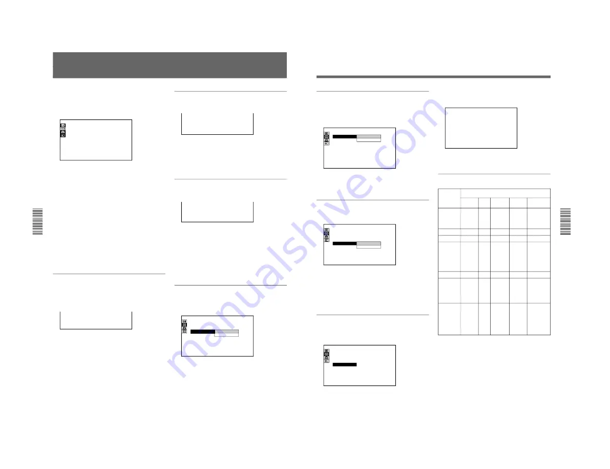
Input signals and adjustable/setting items
Item
DOT PHASE
SIZE
SHIFT
SCAN CONV
ASPECT
H FILTER
BLANKING
Y
: Adjustable/can be set
N
: Not adjustable/cannot be set
Input signal
Video or
S video
N
N
Y
N
Y
N
Y
(TOP and
BOTTOM
only)
15k
RGB
N
N
Y
N
Y
N
Y
(TOP
and
BOTTOM
only)
Compo-
nent
N
N
Y
N
Y
N
Y
(TOP and
BOTTOM
only)
RGB
(preset)
Y
(except
for
HDTV)
Y
Y
Y
(Only for
lower
resolution
than
SVGA)
N
Y
(Higher
resolution
than
XGA)
Y
(HDTV-
GBR,
HDTV-
Y/P
B
/P
R
only)
RGB
(not preset)
Y
Y
Y
Y
N
Y
(Higher
resolution
than XGA)
Y
Summary of Contents for IFB-X2000E
Page 6: ......
Page 85: ...1 79 1998 by Sony Corporation Installation manual 3 865 454 01 1 SU PJ2000 Projector Stand ...
Page 96: ......
Page 112: ......
Page 118: ......
Page 128: ......
Page 188: ......
Page 218: ...9 2 9 2 A B C D E F G H 1 2 3 4 5 FRAME 2 2 FRAME 2 2 ...
Page 227: ...9 11 9 11 A B C D E F G H 1 2 3 4 5 BA BA 4 5 6 7 8 3 2 1 D C B A BA A SIDE SUFFIX 11 ...
Page 243: ...9 27 9 27 A B C D E F G H 1 2 3 4 5 N N A SIDE SUFFIX 11 N B SIDE SUFFIX 11 ...
Page 245: ...9 29 9 29 A B C D E F G H 1 2 3 4 5 BB BB 4 5 6 7 8 3 2 1 D C B A BB A SIDE SUFFIX 11 ...
Page 265: ...9 49 9 49 A B C D E F G H 1 2 3 4 5 M M 4 5 6 7 8 9 10 3 2 1 E D C B A M A SIDE SUFFIX 11 ...
Page 277: ...9 61 9 61 A B C D E F G H 1 2 3 4 5 C C C A SIDE SUFFIX 11 4 5 6 7 8 9 10 3 2 1 E D C B A ...
Page 287: ...9 71 9 71 A B C D E F G H 1 2 3 4 5 GF GM GF GM GM B SIDE SUFFIX 11 GF B SIDE SUFFIX 11 ...
Page 289: ...9 73 9 73 A B C D E F G H 1 2 3 4 5 GF GM GF GM GF A SIDE SUFFIX 11 GM A SIDE SUFFIX 11 ...
Page 291: ...9 75 9 75 A B C D E F G H 1 2 3 4 5 Refer to page 9 74 for Printed Wiring Board GB GB ...
Page 296: ...9 80 9 80 A B C D E F G H 1 2 3 4 5 GC GC A SIDE SUFFIX 11 GC B SIDE SUFFIX 11 ...
Page 298: ...9 82 9 82 A B C D E F G H 1 2 3 4 5 XA XA XA A SIDE SUFFIX 11 XA B SIDE SUFFIX 11 ...
Page 299: ...9 83 9 83 A B C D E F G H 1 2 3 4 5 XA XA Refer to page 9 82 for Printed Wiring Board ...
Page 301: ...9 85 9 85 A B C D E F G H 1 2 3 4 5 Refer to page 9 84 for Printed Wiring Board XB XC XB XC ...
Page 304: ...9 88 9 88 A B C D E F G H 1 2 3 4 5 BM BM BM A SIDE SUFFIX 11 ...


