1-41
20
(GB)
Precautions on Installation
Do not install the projector in the following situations. These installations
may cause malfunction or damage to the projector.
Do not install the projector in an ill-
ventilated place
The projector is equipped with ventilation holes for intake
on the bottom and front and ventilation holes for exhaust on
the left and right sides to prevent internal heat build-up. Do
not block these ventilation holes and allow adequate air
circulation at an installation location.
Do not place any object beside the
projector
If you put something beside the ventilation holes on the
sides, the exhaust may be inhaled into the projector through
the ventilation holes (intake) at the bottom, causing the
internal temperature to rise and thereby activating the
protection circuit. Install the projector so that the exhaust is
not blocked.
Do not install the projector in a location
where temperature or humidity is very high
Avoid installing the projector in a location
where temperature may rise or fall rapidly
Be careful of air-conditioning and heating in a room where
the projector is installed, as sudden changes in temperature
may lead to moisture condensation and cause damage to the
projector.
Avoid installing the projector in a location
subject to excessive dust
Do not use the projector while laying it on
its side
Do not tilt the projector when in use
Avoid tilting the projector more than 20 degrees or installing
it other than on the floor and ceiling. Such installations may
cause malfunctions such as color irregularity or shortening
of lamp life.
Do not cover the ventilation holes
(exhaust)
Do not cover the front ventilation holes; otherwise, internal
heat may build up.
Do not install the projector on a deep-pile
carpet
If you install the projector on a deep-pile carpet, the
ventilation holes (intake) at the bottom may be blocked,
causing an internal heat build-up.
20°
21
(GB)
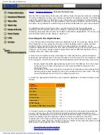
Installations
Screen size
The screen size is the diagonal length of the screen in inches, while the
aspect ratio of the screen is 3:4. The ratio of the screen height, width, and
diagonal is 3:4:5.
If you use a screen with 3:4 aspect ratio whose size is not given in the
table below, you can calculate the screen height and width from the
screen size (inches) as follows.
Calculate at the conversion rate of 25.4 mm to the inch.
Height (mm) = Screen size
×
25.4
×
3
/
5
Width (mm) = Screen size
×
25.4
×
4
/
5
Screen size and dimensions
Tips on the Screen
Screen sizes (inches)
(Diagonal)
Height (mm)
Width (mm)
60
914
1219
80
1219
1626
100
1524
2032
120
1829
2438
150
2286
3048
180
2743
3658
200
3048
4064
250
3810
5080
300
4572
6096
Types of screen
Front projection screen for floor installation
The bead screen is recommended. A screen of this type reflects the
brightest light.
Bead screen
Center of the screen
Brightest picture
Projector
Summary of Contents for IFB-X2000E
Page 6: ......
Page 85: ...1 79 1998 by Sony Corporation Installation manual 3 865 454 01 1 SU PJ2000 Projector Stand ...
Page 96: ......
Page 112: ......
Page 118: ......
Page 128: ......
Page 188: ......
Page 218: ...9 2 9 2 A B C D E F G H 1 2 3 4 5 FRAME 2 2 FRAME 2 2 ...
Page 227: ...9 11 9 11 A B C D E F G H 1 2 3 4 5 BA BA 4 5 6 7 8 3 2 1 D C B A BA A SIDE SUFFIX 11 ...
Page 243: ...9 27 9 27 A B C D E F G H 1 2 3 4 5 N N A SIDE SUFFIX 11 N B SIDE SUFFIX 11 ...
Page 245: ...9 29 9 29 A B C D E F G H 1 2 3 4 5 BB BB 4 5 6 7 8 3 2 1 D C B A BB A SIDE SUFFIX 11 ...
Page 265: ...9 49 9 49 A B C D E F G H 1 2 3 4 5 M M 4 5 6 7 8 9 10 3 2 1 E D C B A M A SIDE SUFFIX 11 ...
Page 277: ...9 61 9 61 A B C D E F G H 1 2 3 4 5 C C C A SIDE SUFFIX 11 4 5 6 7 8 9 10 3 2 1 E D C B A ...
Page 287: ...9 71 9 71 A B C D E F G H 1 2 3 4 5 GF GM GF GM GM B SIDE SUFFIX 11 GF B SIDE SUFFIX 11 ...
Page 289: ...9 73 9 73 A B C D E F G H 1 2 3 4 5 GF GM GF GM GF A SIDE SUFFIX 11 GM A SIDE SUFFIX 11 ...
Page 291: ...9 75 9 75 A B C D E F G H 1 2 3 4 5 Refer to page 9 74 for Printed Wiring Board GB GB ...
Page 296: ...9 80 9 80 A B C D E F G H 1 2 3 4 5 GC GC A SIDE SUFFIX 11 GC B SIDE SUFFIX 11 ...
Page 298: ...9 82 9 82 A B C D E F G H 1 2 3 4 5 XA XA XA A SIDE SUFFIX 11 XA B SIDE SUFFIX 11 ...
Page 299: ...9 83 9 83 A B C D E F G H 1 2 3 4 5 XA XA Refer to page 9 82 for Printed Wiring Board ...
Page 301: ...9 85 9 85 A B C D E F G H 1 2 3 4 5 Refer to page 9 84 for Printed Wiring Board XB XC XB XC ...
Page 304: ...9 88 9 88 A B C D E F G H 1 2 3 4 5 BM BM BM A SIDE SUFFIX 11 ...