8-1
HSR-1/1P
HSR-2/2P
SECTION 8
SPARE PARTS AND OPTIONAL FIXTURES
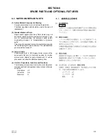
8-1. NOTES ON REPAIR PARTS
(1) Safety Related Components Warning
Components marked
!
are critical to safe operation.
Therefore, specified parts should be used in the case of
replacement.
(2) Standardization of Parts
Repair parts supplied from Sony Parts Center may not
be always identical with the parts which actually in use
due to “accommodating the improved parts and/or
engineering changes” or “standardization of genuine
parts”.
This manual's exploded views and electrical spare parts
list are indicating the part numbers of “the standardized
genuine parts at present” .
(3) Stock of Parts
Parts marked with “o” SP (Supply Code) column of the
spare parts list are not normally required for routine
service work. Orders for parts marked with “o” will be
processed, but allow for additional delivery time.
(4) Units for Capacitors, Inductors and Resistors
The following units are assumed in schematic diagrams,
electrical parts list and exploded views unless otherwise
specified.
Capacitors :
µ
F
Inductors
:
µ
H
Resistors
:
Z
Summary of Contents for HSRA-11
Page 6: ......
Page 74: ......
Page 84: ...9 10 9 10 HSR 1 1P HSR 2 2P ...
Page 91: ......
Page 98: ......
Page 109: ......
Page 111: ...10 15 10 15 HSR 1 1P HSR 2 2P CM 56 CM 56 CM 56 B SIDE SUFFIX 11 ...
Page 112: ...10 16 10 16 HSR 1 1P HSR 2 2P ...
Page 115: ...10 19 10 19 HSR 1 1P HSR 2 2P JC 19 C JC 19 C JC 19 C B SIDE SUFFIX 21 ...
Page 116: ...10 20 10 20 HSR 1 1P HSR 2 2P RP 228 RP 228 RP 228 A SIDE SUFFIX 11 ...
Page 118: ......
Page 141: ...2 3 4 5 I J K L M N O P 11 13 b1 11 13 b1 HSR 1 1P HSR 2 2P 1 ...
Page 166: ...2 3 4 5 A B C D E F G H 11 32 b 11 32 b HSR 1 1P HSR 2 2P 1 ...
Page 180: ...2 3 4 5 A B C D E F G H 11 32 a 11 32 a HSR 1 1P HSR 2 2P 1 ...
Page 188: ...2 3 4 5 A B C D E F G H 11 40 11 40 HSR 1 1P HSR 2 2P 1 ...
Page 204: ...11 56 11 56 HSR 1 1P HSR 2 2P JC 19 C 8 9 JC 19 C 8 9 ...
Page 221: ...2 3 4 5 I J K L M N O P 11 73 b 11 73 b HSR 1 1P HSR 2 2P 1 ...
Page 226: ......

