KP-46WT520/51WS520/57WS520
KP-46WT520/51WS520/57WS520
54
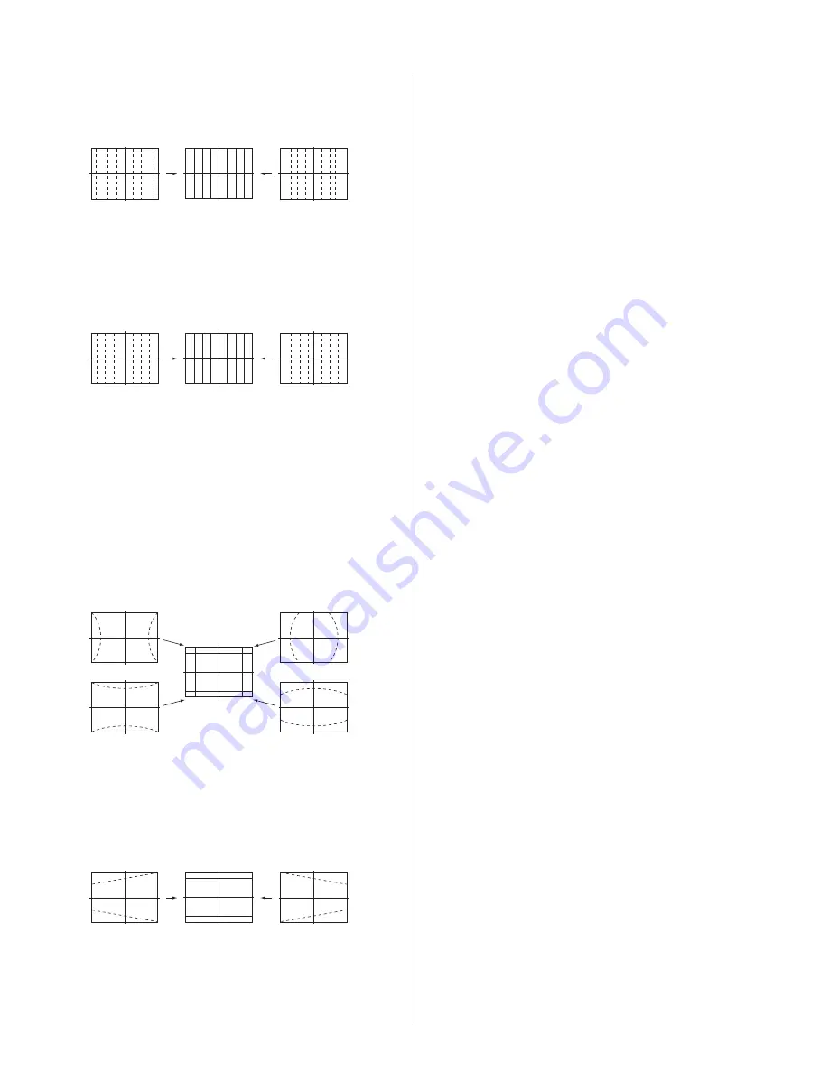
10. Select “GRN MSIZ”, and correct the space intervals for the horizontal
section so the screen is equal.
GRN MSIZ (Horizontally)
Push the joystick
to
Push the joystick
to
11. Select “GRN MLIN”, and correct the sizes of the horizontal line so the
center of the screen is symmetrical left and right.
GRN MLIN (Horizontally)
Push the joystick
to
Push the joystick
to
Note
: The SIZE and LIN, MSIZ and MLIN adjustments
affect each other. If necessary, adjust these mutually.
12. Select “GRN PIN”, and adjust so that right and left vertical lines on
the screen become straight. Adjust so that upper and lower horizontal
lines on the screen become straight.
GRN PIN (Horizontally/Vertically)
Push the joystick
to
Push the joystick
to
Push the joystick
to
Push the joystick
to
13. Select “GRN KEY”, and adjust so that upper and lower horizontal lines
on the screen become parallel.
GRN KEY (Vertically)
Push the joystick
to
Push the joystick
to
Note
: The VPIN and KEY adjustments affect each other.
If necessary, adjust these mutually.
14. Press the “9” button on the remote commander to enter fi ne
adjustment mode.
15. Make the fi ne adjustment so that horizontal lines and vertical lines
become straight.
16. Press the “9” button on the remote commander to return to coarse
adjustment mode.
2) RED ADJUSTMENT
1. Cover the blue CRT lens with a lens caps to allow only the green and
red to show (or use the method shown in the note below for turning off
the CRTs individually without using lens caps).
2. Press the “3” button on the remote commander to select RED mode.
3. Adjust the following items so that red lines overlap with green lines.
•
RED CENT (horizontally/vertically)
•
RED SKEW (horizontally/vertically)
•
RED SIZE (horizontally/vertically)
•
RED LIN (horizontally/vertically)
•
RED MSIZ (horizontally)
•
RED MLIN (horizontally)
•
RED PIN (horizontally/vertically)
•
RED KEY (vertically)
4. Press the “9” button on the remote commander to enter fi ne
adjustment mode.
5. Make the fi ne adjustment so that horizontal lines and vertical lines
overlap with green lines.
6. Press the “9” button on the remote commander to return to coarse
adjustment mode.
Note:
If lens caps are unavailable, you can cut off the unnecessary color
beams by controlling the service mode MCP-RON, GON, BON.
3) BLUE ADJUSTMENT
1. Remove the lens cap from the blue picture lens to display all colors.
2. Press the “3” button on the remote commander to select BLU mode.
3. Adjust the following items so that blue lines overlap with green lines.
•
BLU CENT (horizontally/vertically)
•
BLU SKEW (horizontally/vertically)
•
BLU SIZE (horizontally/vertically)
•
BLU LIN (horizontally/vertically)
•
BLU PIN (horizontally/vertically)
•
BLU KEY (vertically)
4. Press the “9” button on the remote commander to enter fi ne
adjustment mode.
5. Make the fi ne adjustment so that horizontal lines and vertical lines
overlap with green and red lines.
6. Press the “9” button on the remote commander to return `to coarse
adjustment mode.
Note:
When replacing CRTs, adjust the set-up adjustments (2-1 to 2-9)
and the registration adjustment (2-12). When replacing multiple CRTs at
the same time, replace and adjust them individually.
Summary of Contents for Hi-Scan KP-51WS520
Page 17: ...KP 46WT520 51WS520 57WS520 KP 46WT520 51WS520 57WS520 17 WIRE DRESSING 46 Cabinet 46 HB ...
Page 20: ...KP 46WT520 51WS520 57WS520 KP 46WT520 51WS520 57WS520 20 HV Wire HV wire HV Wire HV wire ...
Page 25: ...KP 46WT520 51WS520 57WS520 KP 46WT520 51WS520 57WS520 25 DY Sub DY B DY G DY Excess wire ...
Page 29: ...KP 46WT520 51WS520 57WS520 KP 46WT520 51WS520 57WS520 29 AR Sensor Excess Wire AR Sensor ...


