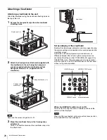
21
Installation and Connections
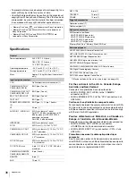
a
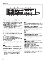
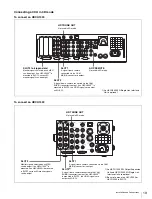
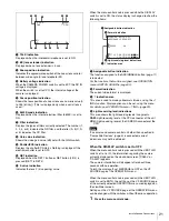
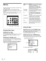
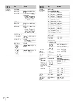
TALK indication
Displayed when the intercom microphone is set to ON.
b
EX (lens extender) indication
Displayed when a lens extender is in use.
c
Zoom position indication
Indicates the approximate position of the zoom lens variator
between wide angle (0) and telephoto (99).
d
Battery voltage indication
When the CAMERA POWER switch is set to EXT, the DC IN
voltage is displayed.
When the switch is set to CCU, the internal voltage of the
camera is displayed.
e
Focus position indication
Shows the focus position of a zoom lens as a numeric value (0
to 255 [infinity]). (This is displayed only when a serial lens is
used.)
f
5600K mode indication
Displayed when the internal electrical filter (5600K) is set to
ON.
g
Filter indication
Displays the types of filters currently selected. The number (1,
2, 3, 4, or 5) indicates the ND filter, and the letter (A, B, C, D,
or E) indicates the CC filter.
h
Gain value indication
Shows the video gain value (dB) set with the GAIN switch.
i
Shutter/ECS indication
Displays the shutter/ECS status. Nothing is displayed if the
electronic shutter is set to OFF.
j
RET indication
Displayed when the RET 1 button or RET button (2/3/4) is
pressed (RET1 to RET4).
k
F-value indication
Indicates the lens F (iris opening) value.
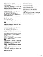
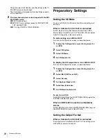
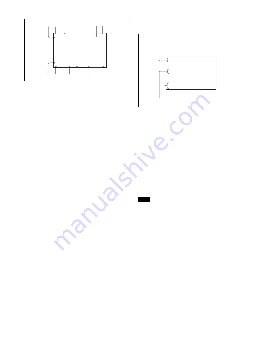
When the menu control knob is pressed while the DISPLAY
switch is set to ON, the status display is changed to show the
following items:
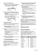
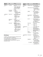
a
Assignable button indication
The function assigned to the ASSIGNABLE button
is indicated.
For the functions that can be assigned, see OPERATION
menu <SWITCH ASSIGN> (page 30).
b
Format indication
The current video format is displayed.
c
‘!’ indication area
This area is used to display abnormal statuses, using the <‘!’
IND> function. Display options can be set, using the menu.
For details, see OPERATION menu <‘!’ IND> (page 29).
d
Light-receiving level indications
This area shows the light-receiving levels in segments.
CAM:
Light-receiving level at the CCU connector of the unit
CCU:
Light-receiving level at the CAMERA connector of the
CCU
If a camera and camera control unit other than specified in
“Compatible Devices”
indications may not be obtained.
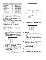
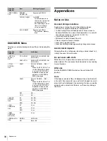
When the DISPLAY switch is set to OFF
When the menu control knob is pressed with the L/BOTH/R
switch set to L or R, the information regarding the camera
currently displayed on the viewfinder screen (“CAM-L” or
“CAM-R”) appears.
The camera information will disappear after about three
seconds with no operation.
To turn the display off, set MESSAGE to OFF on the VF
SOURCE page of the OPERATION menu.
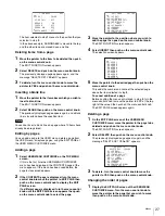
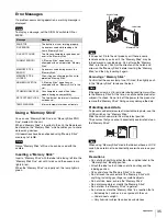
When the menu control knob is pressed with the L/BOTH/R
switch is set to BOTH, the settings on the VF SOURCE page
of the currently selected OPERATION menu are displayed on
the viewfinder screen.
Settings on the VF SOURCE page of the OPERATION menu
can be changed with the switches without the menu operation.
1
Press the menu control knob.
1
2
3
4
5
6
7
8
9
0
qa
F255
12.5V
EX Z55
1A
F5.6
0dB 1/125
RET 1
5600
TALK
Note
1080-59.94i[4:2:2]
ASSIGNABLE REAR:OFF
!5600K :ON
OPT LV CAM:
ss
xxx
xxxb
CCU:
ss
xxx
xxxb
a
Assignable button indication
c
‘!’ indication area
d
Light-receiving level indications
b
Format indication

