


53
Locations and Functions of Parts
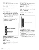
VDA-A Board
a
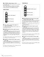
VBS 1, VBS 2 (composite video output 1, 2)
connectors (BNC-type)
The signal from the video camera may be output as two
analog composite signals.
b
PIX OUT (picture monitor output) connector
(BNC-type)
Outputs the video signal for a picture monitor selected
with the PICTURE MONITOR button of an RCP-700
series Remote Control Panel or MSU-900 series Master
Setup Unit.
Character signals or marker signals can be superimposed
on the video signal output through this connector.
For details on these operations, refer to the Master Setup
Unit or Remote Control Panel manuals.
c
WF OUT (waveform monitor output) connector
(BNC-type)
Outputs the video signal for a waveform monitor selected
with the WF MONITOR button of an RCP-700 series
Remote Control Panel or MSU-900 series Master Setup
Unit.
For details on these operations, refer to the Master Setup
Unit or Remote Control Panel manuals.
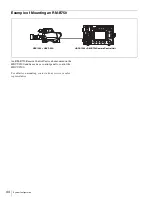
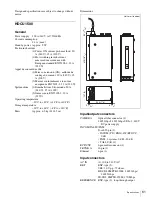
HKCU1003 Multi Interface Unit
(optional)
To reduce the risk of electric shock, fire or injury, do not
open the cabinet. To adjust the internal settings, refer to
qualified service personnel.
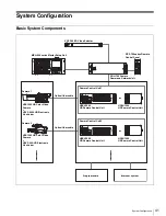
The HKCU1003 consists of an EN-B front board and three
VDA rear boards (A/B/C).
When the EN-B board and one of the VDA rear boards are
installed in the front and rear expansion slots of the unit,
the unit inputs or outputs the following signals.
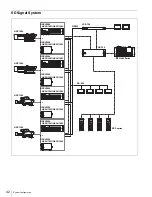
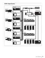
• Outputs SD composite signals, waveform monitor
output signals, and picture monitor output signals
through a VDA-A board.
• Inputs/outputs the frame sequence signal when operating
a 24P system through a VDA-B board.
• Outputs analog component signals or analog composite
signals through a VDA-C board.
When you use either the VDA-A board or the VDA-B
board, insert the EN-B board in the corresponding
expansion slot on the front of the HDCU1000/1500. When
either the VDA-A board or the VDA-B board is installed,
you can insert the VDA-C board in an expansion slot on
the rear panel of the HDCU1000/1500. Don't insert any
board in the corresponding expansion slot on the front of
the HDCU1000/1500.
For details on installation, contact a Sony service or sales
representative.
EN-B Board
a
SD signal format indicators
Either of these indicators lights, corresponding to the SD
signal format.
b
Sub-reference indicators
Either of these indicators lights, corresponding to the
reference signal input via the FRAME REF IN connector
on the VDA-B board.
REF-IN:
Lights when the appropriate reference signal is
input.
UNLOCK:
Lights when the reference signal is not
synchronized with the reference signal input via the
REFERENCE connector of the unit.
Note
VDA-A
1
2
PIX
OUT
WF
OUT
VBS
1
VBS 1, VBS 2 connectors
2
PIX OUT connector
3
WF OUT connector
EN-B
NTSC
PAL
REF IN
UN
LOCK
SC PHASE
ADV
DELAY
1
SD signal format indicators
3
SC PHASE switch
2
Sub-reference indicators


